Main Body
Torsion in Round Shafts
Torsion
Learning Objectives
At the end of this chapter you should be able to complete torsion calculations using:
- General torsion equation
- Polar moment of inertia
- Modulus of elasticity in shear
Shafts are mechanical components, usually of circular cross-section, used to transmit power/torque through their rotational motion. In operation they are subjected to:
- torsional shear stresses within the cross-section of the shaft, with a maximum at the outer surface of the shaft
- bending stresses (for example a transmission gear shaft supported in bearings)
- vibrations due to critical speeds
This chapter will focus exclusively on evaluating shear stresses in a shaft.
All torsion problems that you are expected to answer can be solved using the following formula:
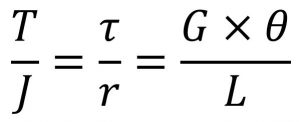
where:
- T = torque or twisting moment, [N×m, lb×in]
- J = polar moment of inertia or polar second moment of area about shaft axis, [m4, in4]
- τ = shear stress at outer fibre, [Pa, psi]
- r = radius of the shaft, [m, in]
- G = modulus of rigidity (PanGlobal and Reed’s) or shear modulus (everybody else), [Pa, psi]
- θ = angle of twist, [rad]
- L = length of the shaft, [m, in]
The nomenclature above follows the same convention as PanGlobal Power Engineering Training System.
Most common torsion problems will indicate the transmitted power (kW) at a certain rotational speed (rad/s or RPM). The equivalent torque can be found with:
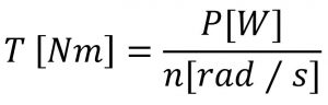
where n[rad/s] = N[rev/min]×2π/60.
Similar to the moments of inertia that you learned before in rotational kinetics and bending of beams, the polar moment of inertia represents a resistance to twisting deformation in the shaft. General formulas for polar moment of inertia are given in Textbook Appendix C.
Note the difference between bending moments of inertia Ic and polar moments of inertia J, and use them appropriately. For instance, if you are dealing with a circular bar:
- Ic = π d4 / 64, if the bar is used as a beam
- J = π d4 / 32, if the bar is used as a shaft
Called Modulus of Rigidity in PanGlobal and Reed’s, the shear modulus is defined (similarly as E) as ratio of shear stress to the shear strain. It is expressed in GPa or psi and typical values are given in Textbook Appendix B. Typical values are lower than Young’s Modulus E, for instance ASTM A36 steel has EA36 = 207 GPa and GA36 = 83 GPa.
The torque deformation of a shaft due is measured by the twist angle at the end of the shaft. This angle of twist depends on the length of the shaft, as shown in the following figure:
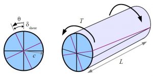 by Barry Dupen [1]
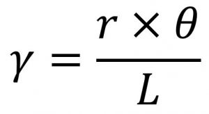
The angle of twist, [radians] is used in the general torsion equation and in estimating the shear strain, γ (gamma), non-dimensional.
Assigned Problems [2]
Solve the following problems using the General Torsion Equation.
Problem 1: To improve an engine transmission, a solid shaft will be replaced with a hollow shaft of better quality steel resulting in an increase in the allowable stress of 24%. In order to keep the existing bearings, the new shaft will have the same outside diameter as the existing, solid shaft. Determine:
(a) the bore diameter of the hollow shaft in terms of outside diameter
(b) the weight savings in percentage, assuming that the steel densities of both shafts are identical
Problem 2: A turbine – generator transmission is rated for 3500 kW at 160 RPM. The shafts, 180 mm diameter and 2 m long, are connected through a flanged coupling with 6 coupling bolts of 40 mm diameter arranged on a pitch circle of 340 mm. If the shaft shear modulus is 85 GPa determine:
(a) the maximum shear stress in the shaft
(b) the shear stress in the bolts
Problem 3: Two identical hollow shafts are connected by a flanged coupling. The outside diameter of the shafts is 240 mm and the coupling has 6 bolts of 36 mm each on a bolt circle of 480 mm. Determine the inside diameter of the hollow shafts, which results in the same shear stress in both, shafts and bolts.
Problem 4: A brass liner, 24 mm thick, is shrunk over a solid shaft of 220 mm diameter. Taking Gsteel = 85 GPa and Gbrass = 37 GPa, determine the maximum shear stress in the shaft and liner if the transmitted torque is 240 kN×m. Also determine the angle of twist if the shaft length is 3.4 m.
Problem 5: Suggest one improvement to this chapter.
