Main Body
Beam Deflection
Deflection
Learning Objectives
Upon completion of this chapter you should be able to calculate:
- The radius of curvature of a deflected beam using theoretical relations
- The maximum deflection of a simply supported beam
- The maximum deflection of various beams using Formula Method and textbook Appendices
Elastic properties of materials are quantified through their Modulus of Elasticity. All materials are elastic to some extent, for example Esteel ≈ 210 GPa, Ecast iron ≈ 160 GPa, Ealuminum ≈ 70 GPa, Econcrete ≈ 40 GPa. In real situations beams subjected to external loads will deflect proportionally to the bending moment and inversely to their stiffness. The overall stiffness of a beam can be expressed as E×Ic where E can be regarded as the material stiffness and Ic as the cross-sectional, or geometrical stiffness.
Review the derivation of the beam deflection covered in detail in Textbook Chapter 10. In practical situations, beam deformation is very small when compared to its length, and as a result the radius of curvature is relatively large.
This radius of curvature can be calculated with
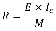
where:
- E is the modulus of elasticity (resistance due to material properties)
- Ic is the moment of inertia about the centroidal axis (resistance due to section geometry)
- M is the bending moment at the section of interest
If the beam is loaded in such a way that the bending moment is constant over a section of the beam (horizontal line in the BM diagram) then the deflection is a circular arc and the radius of curvature is constant.
Take a moment and analyze the above formula… increasing the beam stiffness (E×Ic) will reduce the deflection (large R), while a greater bending moment leads to a smaller radius of curvature (greater deflection/sagging).
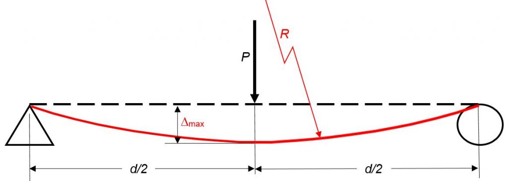
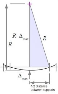
Consider a simply supported beam as in the above diagram. Once the radius of curvature is found, the maximum deflection (at mid span) can easily be geometrically calculated as follows:
![]()
![]()
The Radius of Curvature formula is valid solely for cases where the bending moment is constant. For other cases, geometrical or integration based techniques are involved in determining the beam deflection. Results of these calculations presented in algebraic form are given in engineering handbook of formulas. Most common cases are summarized in textbook Appendix F.
When using “off-the-shelf” formulas, you must first match the beam geometry and loading to one of the given cases. If you are dealing with a more complex loading, such as point loads over-imposed on a distributed load, you can analyze the two loads separately and for the total deflection simply add the constituents.
Assigned Problems
For each problem determine the maximum deflection using the beam equations and compare with the value found using the radius of curvature.
| # | Case: | Loading & Dimensions | Shape & Material |
| Problem 1 | 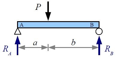 |
|
|
| Problem 2 | 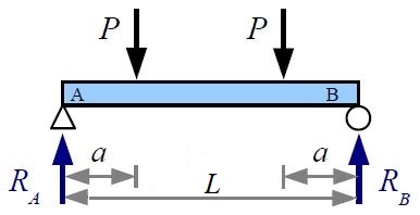 |
|
|
| Problem 3 |  |
|
|
| Problem 4 | 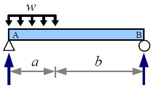 |
|
|
Problem 5: Recommend one improvement to this chapter.
