Main Body
Pressure Vessels
Vessels
Learning Objectives
At the end of this chapter you should be able to
- Identify thin wall or thick wall pressure vessels
- Discuss the difference between longitudinal and circumferential stress
- Demonstrate the derivation of the stress formulas in a thin wall pressure vessel
- Perform thin wall pressure vessel design calculations
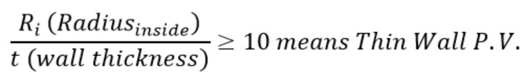
The distinction between thin vs. thick wall pressure vessels is determined by the ratio between the mean radius of the vessel and the thickness of the wall. If this ratio is greater than 10, the vessel is considered a thin wall pressure vessel. If the ratio is less than 10, the vessel is considered a thick wall pressure vessel.
In operation, in a thin wall pressure vessel, stresses developed in the (thin) wall can conservatively be assumed to be uniform. These are the stresses students are familiar calculating using ASME Section I PG-27 or Section VIII Div. I UG-27. In fact, most of the pressure vessels power engineers will work with are of a thin-wall type.
In contrast, a thick wall pressure vessel develops a greater (circumferential) stress on the inside surface of the vessel and it reduces towards the outside diameter. The design calculations for this type of vessels are only covered in the ASME Section VIII (Pressure Vessels) code, Mandatory Appendix 1 (Supplementary Design Formulas).
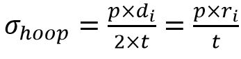
The circumferential stress (or hoop stress) acting on a longitudinal cross-section is derived in the textbook as:
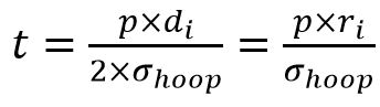
Design problems most typically deal with finding the minimum required wall thickness, therefore the above formula is more useful expressed as:
Hoop stress formula from ASME Section VIII Div. 1 UG-27 is:
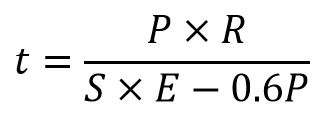
Efficiency “E” is a factor that accounts for loss of material strength due to welds or ligaments. Also note that applying “-0.6P” to the denominator leads to a thicker shell compared to the theoretical formula, and therefore more conservative (or safer). Before using the formula check if the relation is applicable (thin wall).
ASME Section I (Power Boilers) calculates the shell thickness only based on circumferential stress, as follows:
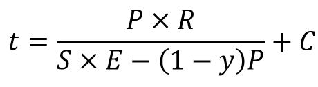
The formulas are quite similar; in the above “y” is a temperature coefficient and C is an added allowance for corrosion or structural stability. Again, the code formula leads to a thicker shell than simply based on derivations.
Longitudinal stress demonstrated and derived in the textbook is derived as:
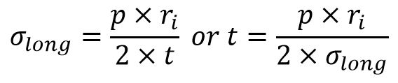
Note that longitudinal stresses are 50% of the hoop stresses and therefore they rarely govern the design. This is the reason ASME Section I does not even require evaluating this stress.
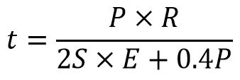
ASME Section VIII Div. 1 requires estimating the vessel thickness based on both stresses, and choosing the largest of the two values. Formula is:
Spherical pressure vessel stress is calculated in the same way as the longitudinal stress. You may conclude that a spherical pressure vessel will require a thinner shell, theoretically one half, than a cylindrical pressure vessel operating at the same pressure and temperature, and therefore it would be a preferred shape. Reality is that while most of that is true, it is difficult to manufacture a spherical shell.
Follow the links for examples of pressure vessels:
- A pressure vessel constructed of a horizontal steel cylinder.
- Spherical gas container.
- LNG carrier ship.
Assigned Problems
- The Pressure Vessel problems must be solved using the theoretical formulas developed in the textbook and NOT the ASME code formulas.
- Always check first if you are dealing with a thin-walled or a thick-walled pressure vessel.
- Thick wall formulas will be provided if necessary.
- Cylindrical vessels require both calculations (longitudinal and circumferential joints); you specify the final answer (minimum wall thickens or MAWP maximum allowable working pressure)
Problem 1: Derive in detail the formulas for longitudinal and circumferential stresses acting on a cylindrical pressure vessel. Briefly discuss the results.
Problem 2: A seamless pipe of 508 mm outside diameter is used as a header in a large power plant carrying steam at 2 MPa pressure. The standard lengths of pipe are butt-welded together to build a continuous pipe. The pipe material, SA-106 Grade C, has minimum Tensile Strength of 485 MPa and a safety factor of 3.5 based is specified. The allowable stress for the butt-welds is 110 MPa. Specify the minimum pipe wall thickness.
Problem 3: A cylindrical tank 36″ diameter and 12 feet long, is used as a compressed air accumulator. The tank is made of ASTM SA-36 rolled steel plate with a wall thickness of 3/4″. Find the maximum allowable working pressure in the tank using a safety factor of 3.5 based on the Ultimate Strength.
Problem 4: A large spherical storage tank for compressed nitrogen is 8.6 m diameter and is constructed using AISI 1040 cold rolled steel plate of 12 mm thickness. The maximum pressure in the tank is 0.66 MPa. If a design factor of 4 based on the Yield Strength is required, does the tank meet the specifications?
Problem 5: Recommend one improvement to this chapter.
