Main Body
Bolted and Welded Joints
Joints
Learning Objectives
At the end of this section you will be able to
- calculate the allowable load of bolted lap joints
- calculate the allowable load of welded joints
Two end plates bolted together and subject to symmetrical tensile loads react to the applied forces through the shear resistance of the bolts and the friction force developed between the plates. The friction force is difficult to evaluate since it depends on the relative roughness of the contact surface and may also be affected by environmental changes (bolts thermal expansion reduces the friction force). As a result, conservative load calculations rely only on the shear resistance of the bolts (or rivets); the extra joint capacity due to friction increases the safety factor.
There are various scenarios that may lead to bolted joints failure, all described in the textbook. When completing these calculations please note the following:
- nomenclature is listed in the textbook on page 6.
- material properties are taken from Textbook Appendices B3 and B4
The following is a summary of the required calculations. The lowest value represents the maximum allowable load.
Shear Failure of the bolts Ps = n×AB×τall×N
- τall, allowable bolt shear stress depends on the the shear location; this can be along the threaded section or the smooth section of the bolt.
Bearing Failure of the Plates PP = d×t×σ-all×N
- σ-all, allowable bearing stress is 1.5 times the ultimate tensile strength of the plate material.
Gross Tensile Failure of the Plates PG = b×t×σG-all
- σG-all, allowable gross tensile stress of the plate is 60% of the yield strength of the material
Net Tensile Failure of the Plates PN = (b×t-NF×dH×t)×σN-all
- σN-all, allowable net tensile stress is half of the ultimate tensile strength of the plate material
Welded joints are often preferred to bolted joints because they are simpler, easier to complete, relatively stronger and can provide a sealed assembly. However, they cannot be dismantled for maintenance or replacing parts.
When completing weld calculations please note the following:
- nomenclature is listed in the textbook on page 6.
- use Appendix B6 for common weld and plate size; use Appendix B5 for weld strength of common electrodes
Weld Strength Pweld = L×fweld
Gross Tensile Strength of the Plates – same as for bolted joints
Assigned Problems [1]
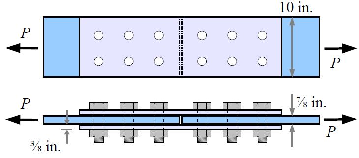
Problem 1: Two A992 steel plates are joined with two A992 steel splice plates and twelve 1 in. diameter A490 steel bolts with threads in the shear planes. Calculate the maximum load that the joint can support, in kips.
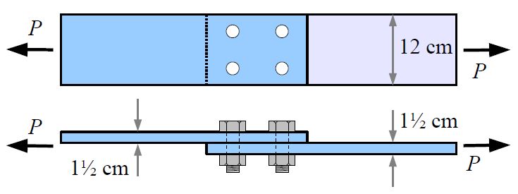
Problem 2: Two A36 steel plates form a lap joint with four 20 mm diameter A307 steel bolts. Calculate the maximum load that the joint can support, in kips.
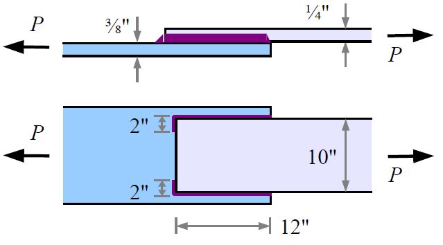
Problem 3: Two A36 steel plates are welded with an E70 electrode.
- What is the minimum recommended weld size for this joint? [in.]
- What is the joint strength? [kips]
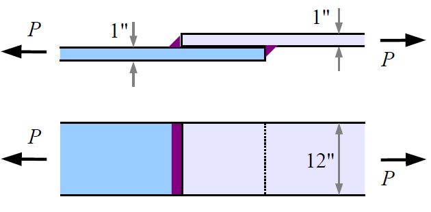
Problem 4: Two A36 steel plates are welded as shown with a 3/8 in. fillet weld using an E60 electrode. What is the joint strength?
Problem 5: Suggest on improvement to this chapter.
- From Problem Set - Spring 2017, by Barry Dupen ↵
