Main Body
Beam Reactions and Diagrams
Diagrams
Learning Objectives
At the end of this chapter you should be able to:
- Determine the reactions of simply supported, overhanging and cantilever beams
- Calculate and draw the shearing force and bending moment diagrams of beams subject to concentrated loads, uniform distributed loads and combinations of the two.
Beams are structural elements with various engineering applications like roofs, bridges, mechanical assemblies, etc. In general, a beam is slender, straight, rigid, built from isotropic materials, and most important, subjected to loads perpendicular to their longitudinal axis. If instead of perpendicular loads the same structural member would be subjected to longitudinal loads it would be called column or post. If the same member would be subjected to a torque, it would be called and treated as a shaft. Therefore, when identifying mechanical or structural components, consideration of the manner of loading is very important.
Note that when it comes to orientation, beams can be horizontal, vertical or any inclination in between (like submerged plates analyzed in fluid mechanics)… provided the loading is perpendicular to their major axis.
Beam supports:
| Support Type | Looks like | Symbol | Reactions |
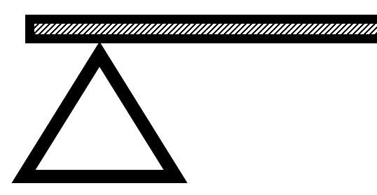
Roller, also called
|
 |
|
|
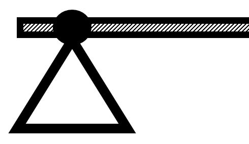
Pinned, also called
|
 |
|
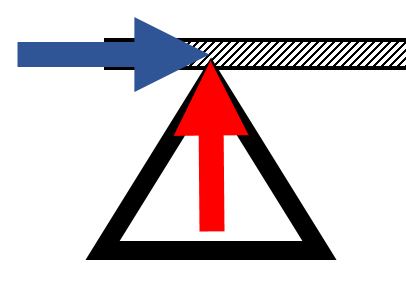
|
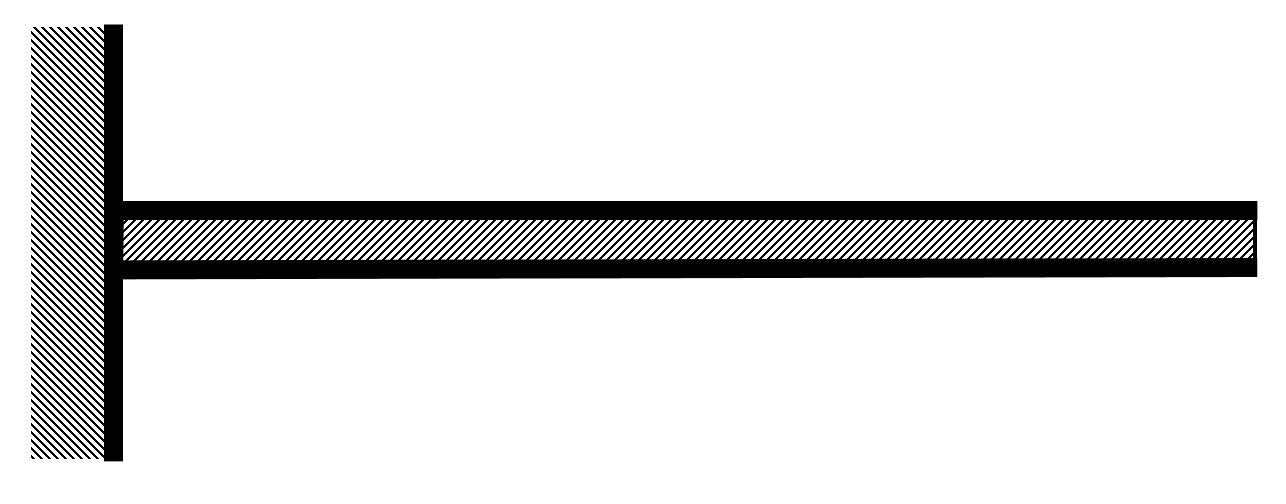
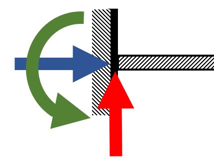
| Fixed | 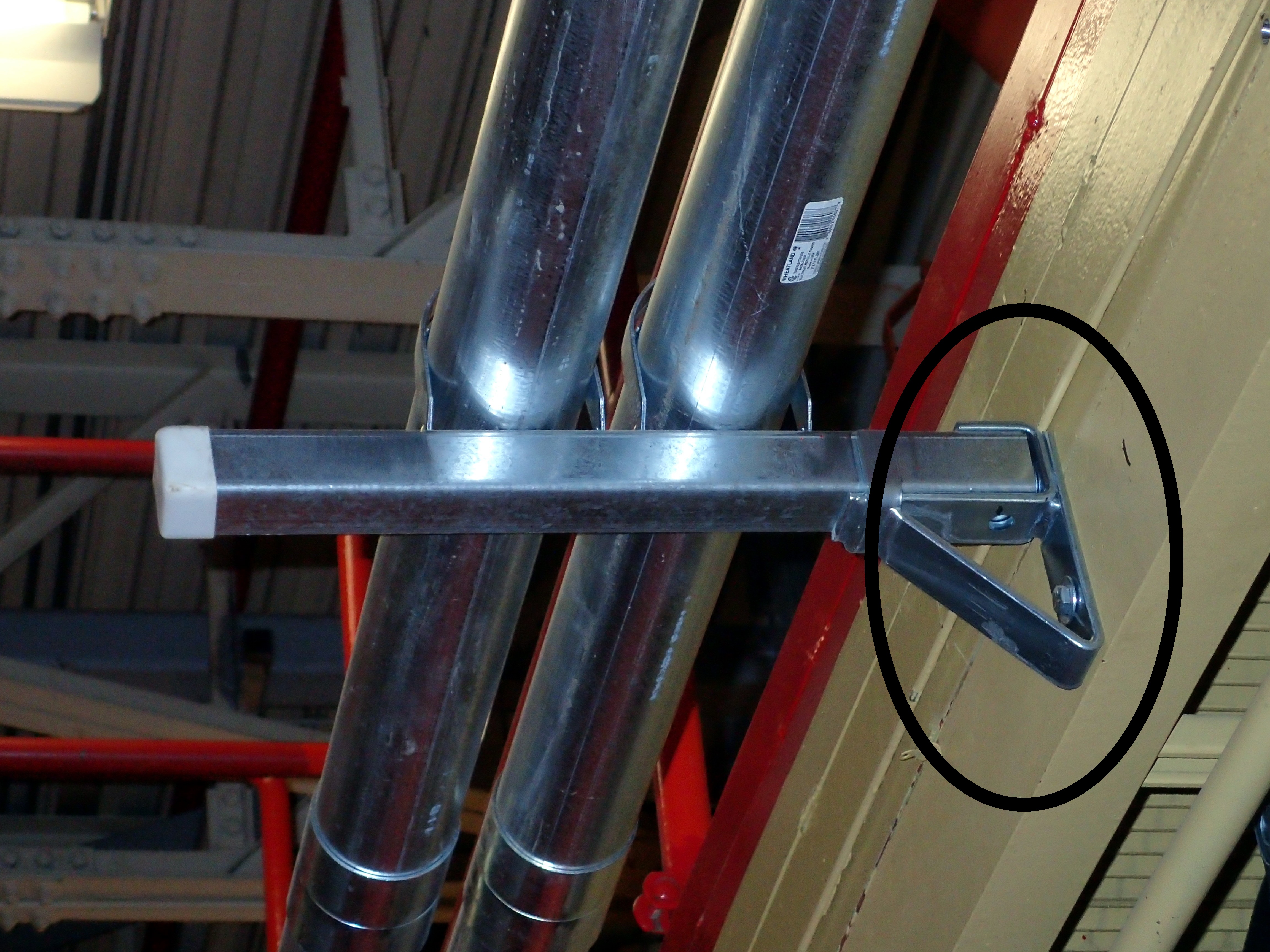 |
 |
|
Beam Loads[1]:
| Loads | Symbol | Examples | Covered |
Point, also called
|
 |
|
Yes |
| Uniform Distributed | 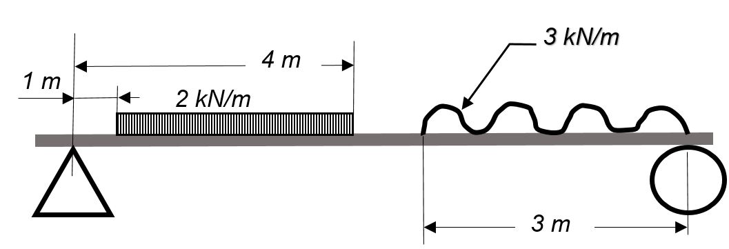 |
|
Yes |
| Variable Distributed | 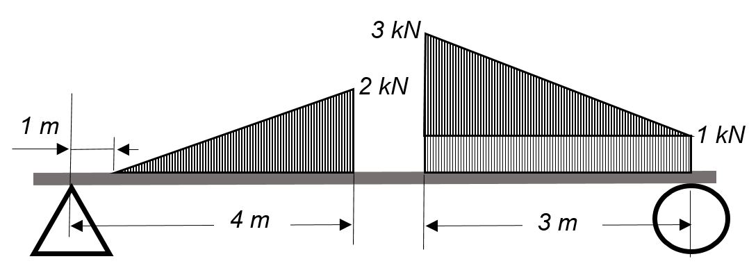 |
|
Yes |
| Concentrated Moments | 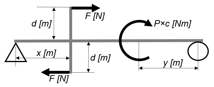 |
|
No |
Beam types:
| Types | Diagram | Examples | Covered |
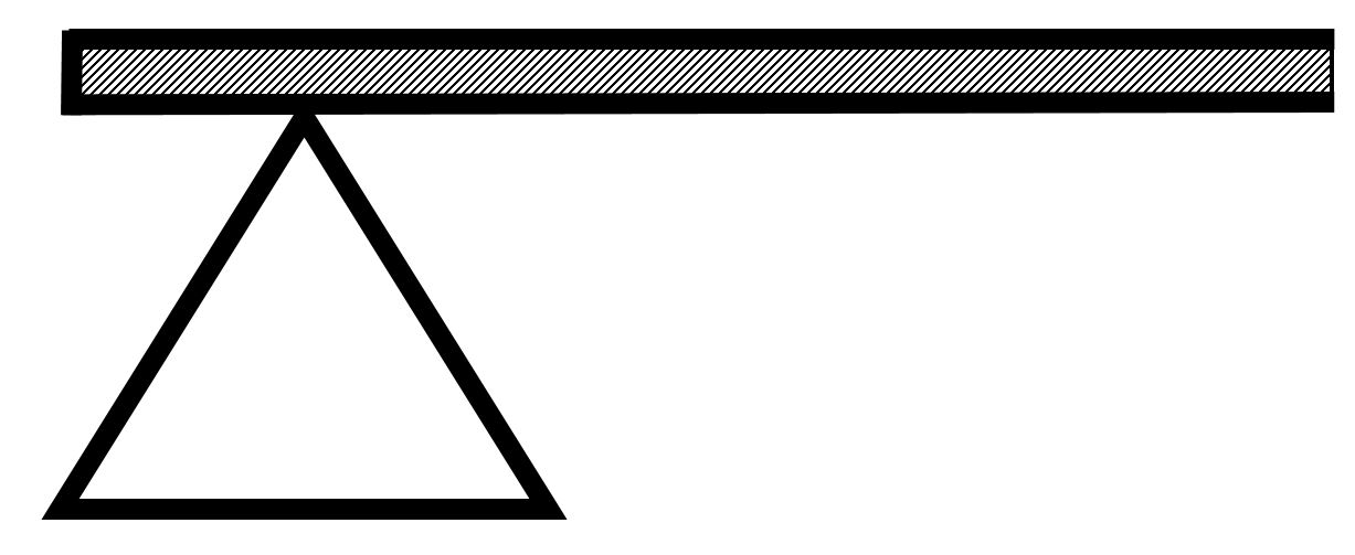
| Simple beams, or simply supported | 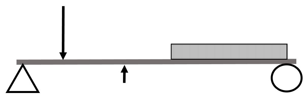 |
|
Yes |
| Overhanging beams | 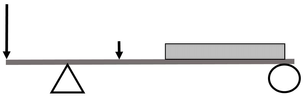
|
|
Yes |
| Cantilever beams | 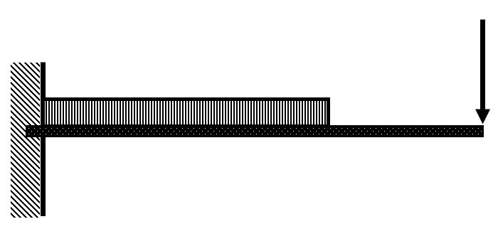 |
|
Yes |
| Compound beams | 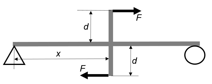 |
|
No |
| Continuous beams | 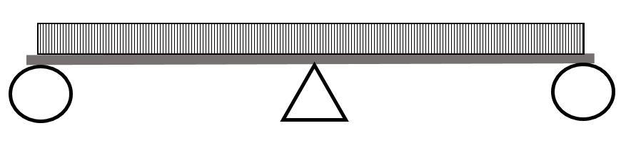 |
|
No |
When solving for reactions, the following steps are recommended:
- Draw the beam free body diagram
- Replace the uniform distributed load (if any) with the equivalent point load
- Solve ΣMA = 0 (sum of moments about support A). This will give you RB (reaction at support B).
- Solve ΣMB = 0. This will give you RA.
- Using RA and RB found at steps 3 and 4 check if ΣV = 0 (sum of all vertical forces) is satisfied.
- Note that steps 4 and 5 can be reversed.
- For a cantilever beam use ΣV = 0 to find the vertical reaction at the wall and ΣMwall = 0 to find the moment reaction at the wall. There is no other equation to validate your results.
Please note:
“Shearing forces are internal forces developed in the material of a beam to balance externally applied forces in order to secure equilibrium of all parts of the beam.
Bending moments are internal moments developed in the material of a beam to balance the tendency for external forces to cause rotation of any part of the beam.” [3]
The shear force at any section of a beam may be found by summing all the vertical forces to the left or to the right of the section under consideration.
Similarly, the bending moment at any section of a beam may be found by adding the moments from the left or from the right of the section considered. The moment’s pivot point is the location under consideration.
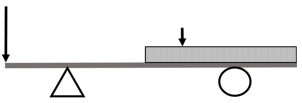
By convention, internal shearing forces acting downward are considered positive. They counteract upward external forces. Therefore, when representing the shear forces you can draw them in the direction of external forces. This is visually easier than following the sign convention.
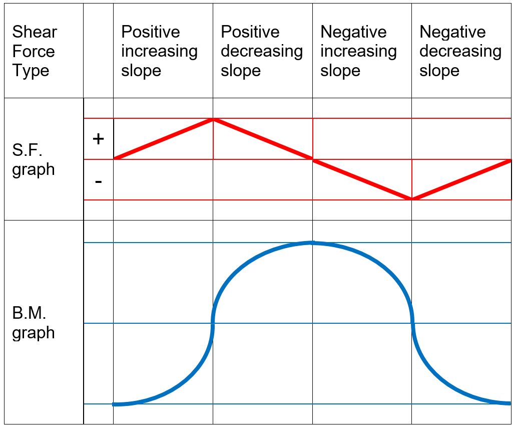
Clockwise moments, conventionally, are considered negative while counter-clockwise moments are considered positive. When representing the bending moment variation, consult the following table showing qualitative bending moment curves dependent on the shape of the shear force graphs.
 .
. 
When drawing the shear force and bending moment diagrams, while the sign convention is important, consistency is crucial. For instance, consider a simple beam loaded with a point load applied on a UD load. Starting the diagrams at support A, looking towards the page, will generate the following:
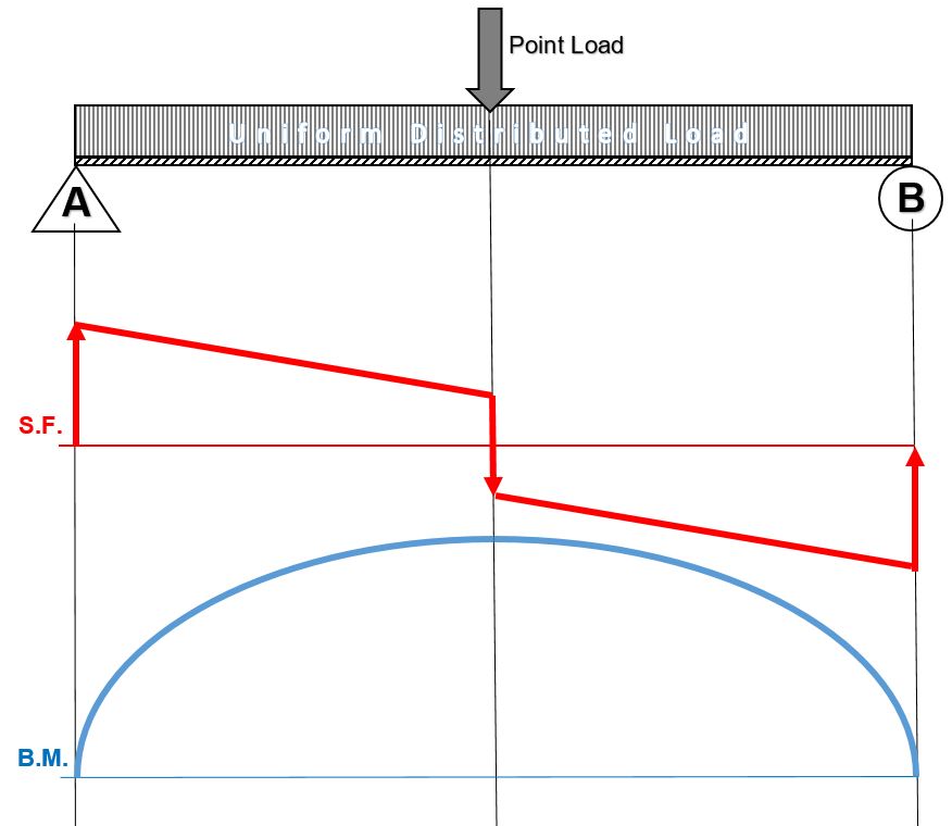
Now, flip the beam horizontally 180º (or change the observation point, looking at the beam from the opposite side) and draw the diagrams, starting from the same point A. The diagrams will appear as follows:

Note that, while the shear force diagrams appeared to be mirrored images (flipped horizontally), the bending moment diagram is not affected. Additionally, the most important result of this analysis, illustrates that maximum shear force and bending moment magnitudes will always be the same.
Beam diagrams check points
When drawing the beam diagrams please observe the following:
Shear Forces Diagrams:
- At the ends of a simply supported beam the shear force is zero.
- At the wall of a cantilever beam the shear force equals the vertical reaction at the wall. At the beam’s free end the shear force is zero.
- On any beam segment where no loads are applied, the shear force remains constant (horizontal line).
- A point load or reaction on a shear force diagram generates an abrupt change in the graph, in the direction of the applied load.
- A uniform distributed load acting on a beam is represented by a straight line shear force with a negative or positive slope, equal to the load per unit length.
Bending Moments Diagram:
- At the ends of a simply supported beam the bending moments are zero.
- At the wall of a cantilever beam, the bending moment equals the moment reaction. At the free end, the bending moment is zero.
- At the location where the shear force crosses the zero axis the corresponding bending moment has a maximum value.
- The shape of the bending moment curve between two points on the beam is as shown in the above two tables.
- The change in bending moment between two points on the beam equals the area under the shear force diagram between the same two points.
The above guidelines will assist you in generating the beam diagrams; they also serve as a check.
Assigned Problems
Calculate the beam reactions and draw the shear force and bending moment diagrams for the following beams.
When solving beam diagrams in class and at home you may check your answers by using this free online beam calculator: SkyCiv Cloud Engineering Software
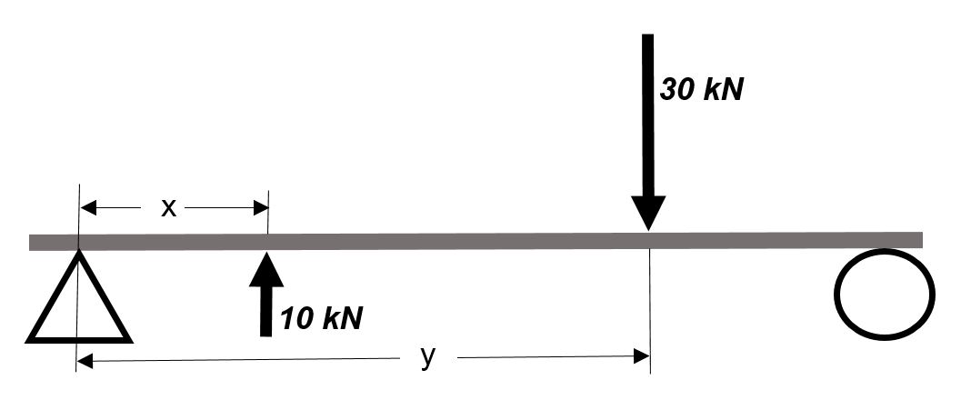
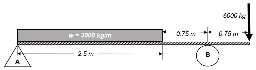
Problem 1: State the maximum shear force and bending moment values.
Problem 2: State the maximum shear force and bending moment values.
Problem 3: A 24 meters long beam is simply supported at 3 meters from each end. The beam carries a point load of 18 kN at the left end and 22 kN at the right end of the beam. The beam weighs 400 kg/m. Sketch the beam diagrams and determine the location on the beam where the bending moment is zero.
Problem 4: A simple overhanging beam 112 ft long overhangs the left support by 14 ft. The beam carries a concentrated load of 90 kips 12 ft from the right end and a uniform distributed load of 12 kips/ft over a 40 ft section from the left end. Sketch the beam diagrams and determine the shear force and the bending moment at a section 50 ft from the left end.
Problem 5: Suggest an improvement to this chapter.
- Click on the diagrams to expand ↵
