Main Body
Beam Stress due to Bending Moments
Bending Stress
Learning Objectives
After completing this chapter you should be able to:
- Use the flexure formula to calculate maximum bending stress
- Design beams carrying loads safely
- Determine the required Section Modulus of a beam
- Select standard structural shapes to be used in a given beam problem
Consider a simply supported beam subjected to external downward loads. The beam will deform (deflect) in such a way that the top surface of the beam cross-section will be under compression while the bottom surface will be in tension. At some location along the vertical axis of the beam, the stress will be zero; this location is the centroid of the cross-section, also called the neutral axis.
To determine the maximum stress due to bending the flexure formula is used:
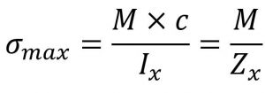
where:
- σmax is the maximum stress at the farthest surface from the neutral axis (it can be top or bottom)
- M is the bending moment along the length of the beam where the stress is calculated
- if the maximum bending stress is required then M is the maximum bending moment acting on the beam
- Ix is the moment of inertia about x (horizontal) centroidal axis
- c is the maximum distance from the centroidal axis to the extreme fiber (again, this can be to the top or bottom of the shape)
- Zx is called section modulus and is a term that combines the moment of inertia and the distance to the extreme fiber (Zx = Ix / c)
The flexure formula is valid if the following criteria are met:
- the beam is straight, relatively long and narrow and of uniform cross-section
- all the loads act perpendicular to the longitudinal axis of the beam
- the resulting stress is below the limit of proportionality of the material
- the beam material is homogeneous and has equal strength in tension and compression
- if the material has different strengths in tension and compression (example cast iron or other anisotropic materials) then separate calculations are required for both tension and compression surfaces
- no twisting, buckling or crippling occurs
Design problems may follow different scenarios:
- calculate the beam cross-sectional dimensions (find the minimum section modulus Z and choose a standard shape of greater stiffness), given the beam geometry, loading and material.
- select the beam material (find maximum working stress and choose a material of greater strength), given the beam dimensions, loading and dimensions/shape.
- determine if a beam is safe (find actual working stress and compare to design stress), given the beam dimensions, loading and material.
Assigned Problems
Note: if not specified, use σdesign = 0.6×σYS, where σYS is the Yield Strength, from textbook Appendix B.
Problem 1: A simply supported beam, 9.9 meters long, is loaded with concentrated loads as follows:
- 40 kN a@ 1.2 m from left end
- 10 kN @ 3.7 m from left end
- 10 kN @ 6.2 m from left end
- 10 kN @ 8.7 m from left end
The beam is constructed using W200×100 I-beam profile from AISI-1020 cold rolled material. AISC recommends that the maximum bending stress for building-like structures under static loads be kept below 0.66×Sy. Does this construction meet the design requirements?
Problem 2: A pipeline is simply supported above ground on horizontal beams, 4.5 m long. Each beam carries the weight of 20 m Sch 40 DN-600 pipe (see PanGlobal Academic Extract), filled with oil of 0.9 SG. Assuming that the load acts at the center of the beam, calculate the required section modulus of the beam to limit the bending stress to 140 MPa; then select the lightest SI W-beam that satisfies the criteria.
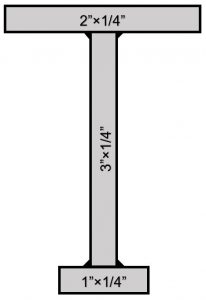
Problem 3: The figure shows the cross-section of a beam built from aluminum 6061-T6. The beam is used as a 45 in. long cantilever. Compute the the maximum allowable uniformly distributed load it could carry while limiting the stress due to bending to one-fifth of the ultimate strength.
Problem 4: Design a walkway to span a newly installed pipeline in your plant. Rigid supports are available on each side of the pipeline, 14 ft apart. The walkway has to be 3.5 ft wide and be able to support a uniformly distributed load of 60 lb/ft2 over its entire surface. Design only the deck boards and the side beams. Use any timber sizes and material grades from textbook Appendix E or others of your own design.
Problem 5: Suggest one beam design problem that you would consider relevant and useful for Power Engineers.
