27 Communication System Model
Objective:
To investigate the response of a communication channel to a pulse signal.
Procedure:
1 . Using Matlab write the code to model the following impulse response (h(t)) of the channel in terms of step function. Note that Th=1 second
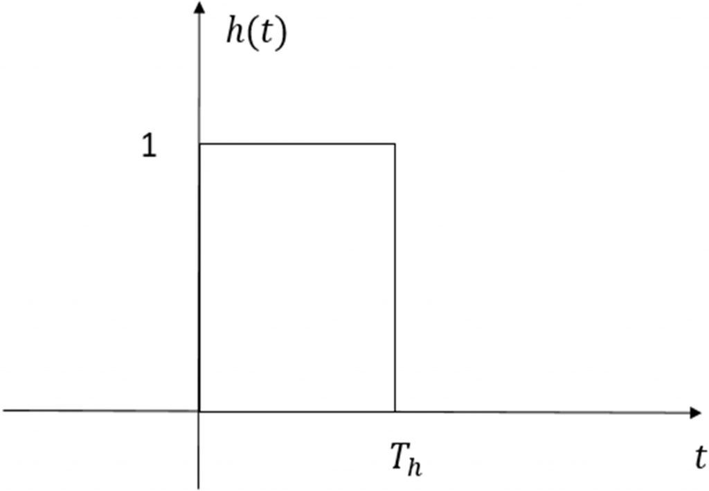
2. Plot the impulse response in Matlab.
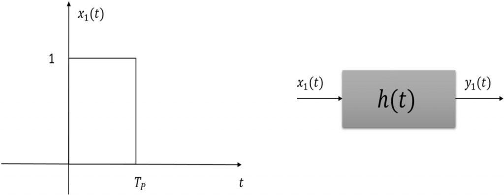
3. Signal x1(t) with Tp=2 seconds goes through the communication channel with impulse response h(t). Using Matlab find the output signal of the communication channel.
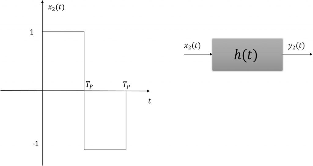
4. Apply x2(t) signal with Tp=2 seconds to the communication channel with impulse response h(t). Use Matlab to sketch the output signal of the communication channel. If the response of the positive and negative portions of x2(t) are represented by “1” and “0” symbols respectively, do you see inter-symbol interference when the signal x2(t) passes through the communication channel? What solution can you suggest to avoid the symbol interference?
5. Cascade two communication channels as shown in the figure below and apply the input signal x1(t) . Plot the output signal z1(t).
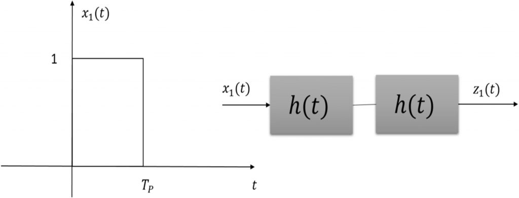
6. What will be the output if three communication systems with impulse response h(t) are cascaded and the signal x1(t) is applied to the input? What if there are 4 cascaded systems?
7. Can you guess what will happen to the output if cascade more number of communication systems with impulse response h(t) and apply the signal x1(t) ?
