13 DC motors
DC motors are widely used in numerous feedback systems and robotic applications. The DC motor are modeled in order to analyze the performance of such systems.
Objectives
The following objectives will be covered as you go through the experiment procedure.
- Derive the transfer function of the DC motor with gearbox system
- Apply an input signal to DC motor and record the output
- Simulate the DC motor system in Simulink
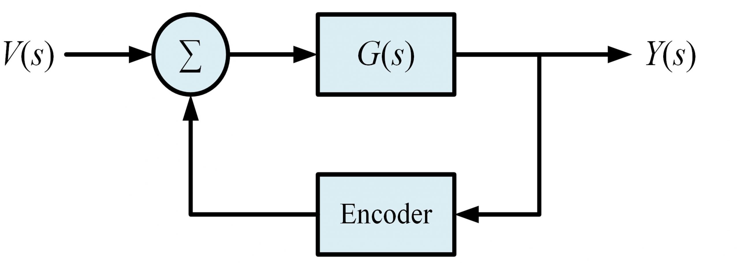
- Control the DC motor with gearbox system using an encoder feedback
Procedure
1. Assume that you have a DC motor with gearbox and the input to the system is voltage and the output of the system is the angular position or angular velocity.
a) Find the transfer function of this system mathematically for both types of outputs (angular velocity and position).
b) Use some practical values for the parameters of the DC motor and the gearbox. For this purpose, research some existing DC motors in the market and try to find the parameters.
2. Use MATLAB to apply an input signal such as Step function, Pulse function (choose an arbitrary frequency or duty cycle), Triangle function (choose an arbitrary frequency) or any other type of input signals that you like to apply to the system. Choose an appropriate amplitude for your signal.
a) Find the output of the system using MATLAB.
b) Record the input and output signals of the system and save them as a file (.mat file). Your .mat file should have t (that holds time values), the input signal values applied to the system, and the output values.
c) Create a .mat file for angular velocity being the output and another .mat file when the output is angular position.
3. Build the system in Simulink. Use Simulink to apply your input to this system and plot the results of both angular velocity and angular position on the oscilloscope in Simulink.
4. Now assume that you don’t know the transfer function and parameters of the system and just the .mat files are available. Use the .mat file related to the angular velocity as output. Try to find the transfer function of your system. [Assume someone gives the .mat file and tells you that the file is generated by performing measurement on a system and asks you to find the transfer function]. Try to find a transfer function that gives you similar results as the results obtained in the .mat file. Describe your solution in detail.
5. Assume that the DC motor is equipped with an optical encoder that gives the position information. The transfer function of the encoder is 3.11 volts/radians. Make the following feedback system to control the DC motor and the gearbox system whose transfer function is represented as G(s). The feedback system including the optical encoder in shown in Figure 7.1. Repeat Steps 1-4 for the feedback system.