7 Electrical system
Power grids are made up of different components so that they can deliver electricity to consumers at the lowest cost and highest quality. Although in current networks there is an attempt to produce energy next to the place of consumption, due to different environmental conditions and of course the distance of major production sites and large power plants from the place of consumption, the need for a transmission system to connect consumers (L) and producers is essential.
The most important part of the network is the generator (G). Its task is to regulate and maintain the voltage and frequency of the network in a certain range. This is done by the turbine inlet power and excitation control system. The steam, gas, and hydropower plants used in the grid are mostly synchronous and can only generate power at a certain rotational speed.
As it was mentioned above, there is a need for a transmission line to connect the power plant to the consumption sources. Each transmission line can contain several different lines and protective elements depending on the type and location of the transmission line. To reduce losses in these lines, we try to use high voltages such as 230 kV and 400 kV. Of course, this voltage is very dangerous for humans, so at the time of consumption, the voltage must be reduced again to 400 volts (line voltage).
Step-down or -up transformers (T) are used to regulate the voltage. Each transformer is modeled as an impedance in the network.
A Lightning arrester is a suitable element in power grids that is used to protect the line against lightning. The arrester operates on the basis of transmitting above-normal voltage to the ground and allows the line to pass low and normal line voltages. The arrester building consists of several resistors and several air gaps, which if the voltage exceeds the allowable limit, the insulating property of the air in these distances is destroyed and with a voltage spark, voltage is transferred to the ground.
In the last stage, electricity is transferred to the distribution network. In this network, which can include industrial, commercial and residential consumers (L), the input voltage level (about 63 kV) must be reduced once again to reach the voltage level of 20 kV and then 400 volts.
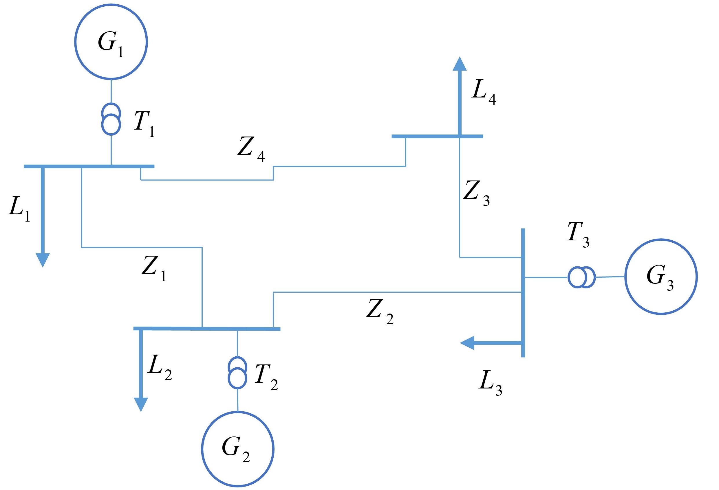
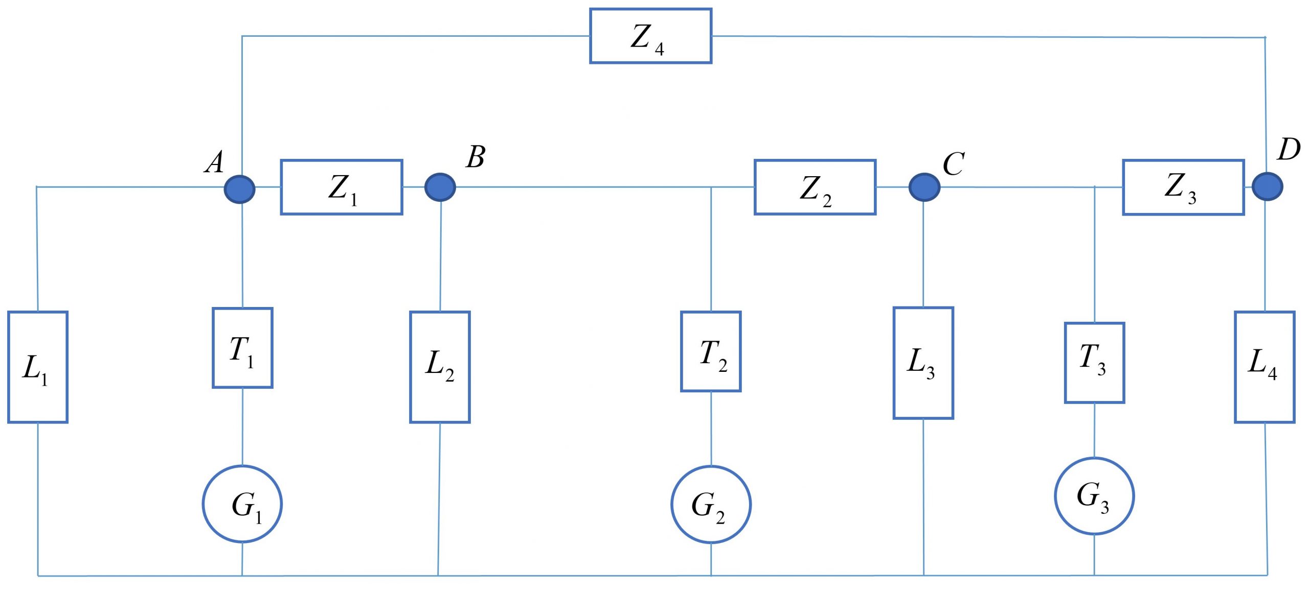
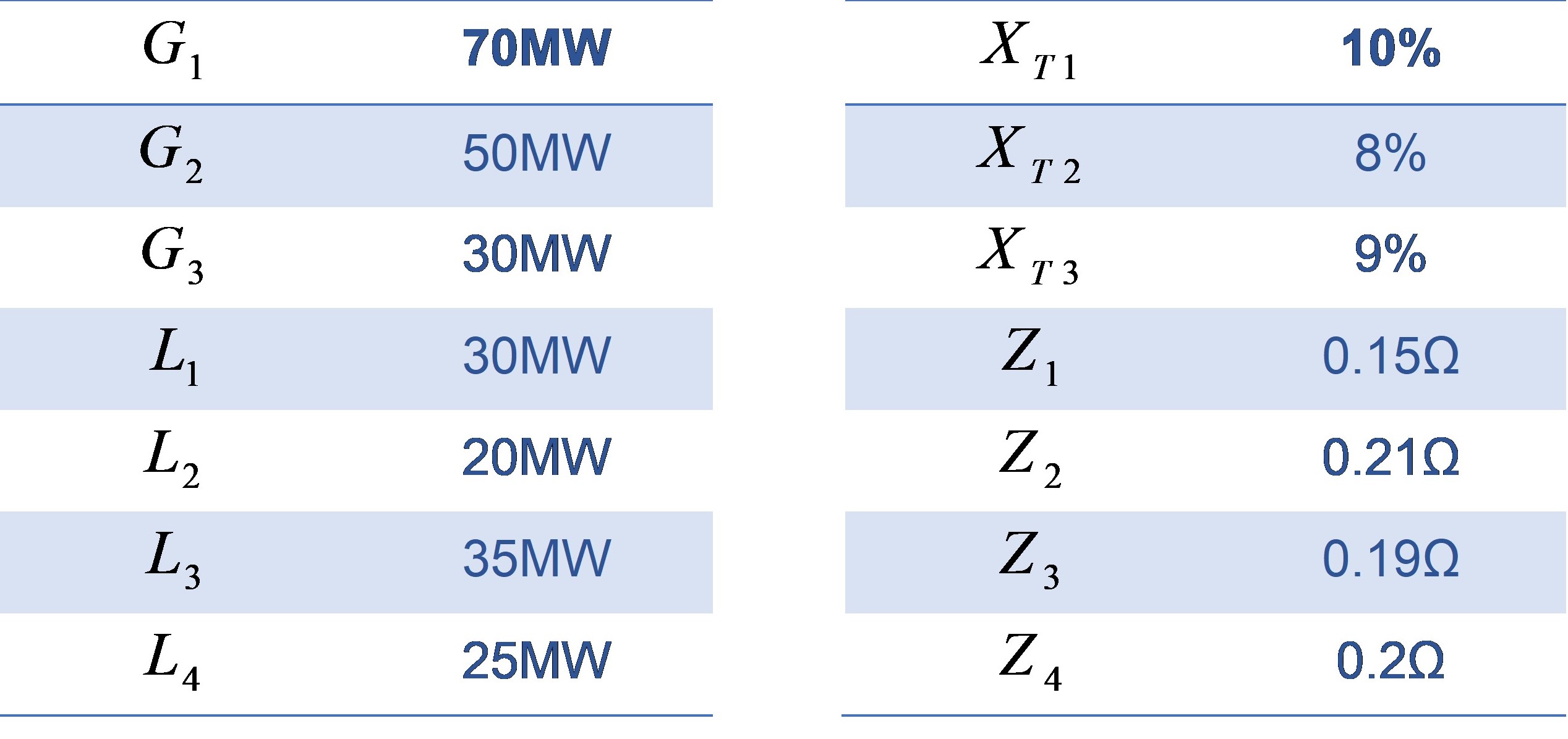
In Figure 4.1, you can see a practical network with different parts. This grid has three phases but to make the calculation easier, we can work with a single-phase circuit which is shown in Figure 4.2 . All the parameters for the grid can be found in Table 1. Note that T1 is a three-phase 20KV/6KV, 70MW transformer, T2 is a three-phase 20KV/11KV, 50MW transformer, and T3 is a three-phase 20KV/6KV, 30MW transformer, and Sb (complex power number)=100.
Table 4.1– Grid parameters
Objectives
The following objectives will be covered as you go through the experiment procedure.
- Derive the differential equations and transfer function for an electrical grid
- Become familiar with basic MATLAB Simulink and Powerlib library
- Examine the system response to some realistic inputs and situations
Procedure
1. For the grid schemes in Figure 4.1 and Figure 4.2, use KVL and KCL to calculate the parametric differential equations for the grid.
2. Using the equations obtained in the previous part:
a) Determine all natural frequencies of the system parametrically. What parameter can change them to instability? (characteristic roots)
b) Derive the transfer function from voltage G1 to L4. Then, plug the values from Table 4.1 in the equation where the voltage and power base (Use PU) are standardized. Is this system stable?
3. Find the power flow through the grid and the voltage in A, B, C, and D.
4. Use MATLAB Simulink to simulate the grid using Powerlib library. Use induction motors as your load, and find the voltage in A, B and C in Figure 4.2. Use 5% of the 5th harmonic in L3 and L2 and find the voltage again (System response in other frequencies). Verify your answer with the transfer function in Part 2.
5. Using Simulink and Powerlib library:
a) find the lightning effects on voltage in A, B, C, and D. Consider the lightning struck A and use the default configuration in Simulink.
b) Derive the impulse response of the transfer function in Part 2.
c) Is voltage in D the same as in Part a and b?
d) Explain how this lightning incident can damage the system or make it unstable.
