23 Filtering voice signal
Background
The behaviour of a system can be analyzed in both time and frequency domains with time response and bode plots, respectively. Since these behaviours may not suit our needs, we can alter them with different filters. A transfer function contains some zeros and poles which their positions can be analyzed to design a suitable filter.
Generally, filters could be discussed in analog and digital domains. Analog filters are mostly used in electronic circuits while digital filters are used in digital systems such as computers. However, we can design analog filters in a digital environment such a computer software. One of the most popular applications of filters is audio filtering which is utilized in noise removal, audio separation and even encoding/decoding of audio signals.
There are 4 commonly used types of filters:
1) Low-pass filter:
A Low-pass filter has a gain above zero in low frequencies which allows them to pass the low frequency signals effectively. This gain significantly drops after a certain frequency to values close to zero. That frequency is called the “Cut-off Frequency”. In real world situations, filters are not ideal.
We can see the frequency response of an ideal filter versus a real world filter in Figure 12.1.
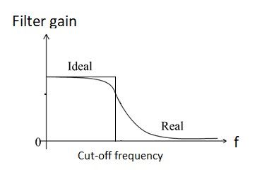
A low-pass filter of order N has a transfer function like (a/(s+b))N . In low frequencies, s is close to zero so the gain is approximately (a/b)N . Poles (or pole) of this transfer function are on -b. This filter is mostly used to remove noise, a high frequency sound wave, from audio signals.
2) High-pass filters:
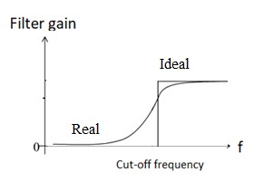
In contrast to low-pass filters, high-pass filters have a gain close to zero in low frequencies. This gain starts to rapidly increase from cut-off frequency before reaching a constant value. A high-pass filter of order N has a transfer function like (as/(s+b))N . In very high frequencies with infinite s, gain is approximately aN . Similar to low-pass filters, we have a gain of (1/√2) at cut off frequency.
You can see the frequency response of an ideal high-pass filter alongside with its non-ideal kind in Figure 12.2.
3) Band-pass filters:
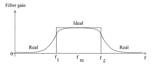
Combining a low-pass filter with cut-off f1 and a high-pass filter with cut-off f2, results in a filter which passes frequencies only in a specific range. From frequency f1 to f2, signals are passed with some values of gain and outside of this range, gain is close to zero. Midpoint of this frequency is called “Center Frequency” fm where fm = SQRT( f1 f2 ).
In general , the transfer function of this filter is
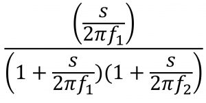
Gain of the filter at points f1 and f2 equals (1/sqrt(2)) ×fm. Just like above filters, there are ideal and non-ideal forms of this filter shown in Figure 12.3.
4) Band-stop filter:
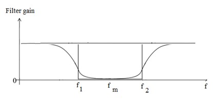
These filters’ operation opposes the operation of band-pass filters. There is a range of frequencies from to where the filter has a gain close to zero. The gain increases while moving out of this range to reach a nearly constant value. We can say that this filter is comprised of two high-pass and two low-pass filters in parallel. There is also a center frequency, fm, where fm = SQRT( f1 f2 ). The general Transfer Function of a band-stop filter is:
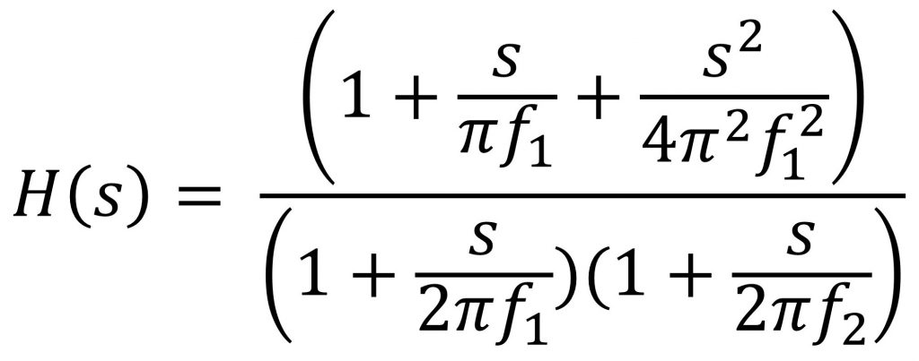
Frequency response of an ideal and non-ideal band-stop filter is depicted in Figure 12.4.
Objectives
The following objectives will be covered as you go through the experiment procedure.
- Design analog filters in MATLAB with specific pass and stop frequencies
- Explain the impact of modifying the location of poles and zeros and changing the order of filters
- Remove the noise from a digital audio file using a low-pass filter
- Remove a sound with specific range of frequency from a digital audio file using a band-stop filter
- Split the sounds from a digital audio file using high-pass and band-pass filters
Procedure
- Open the audio file number one using the audioread command. It contains high frequency components that we want to filter out.
a) What kind of filter should we use?
b) Design a filter using zpk(zeros,poles,gain). Plot the bode diagram using bode command. Is the filter correctly designed?
c) Apply your filter to the audio file using the lsim Describe the changes.
d) Change the gain of your filter. How does the output change?
e) Increase the order of your filter. How does the output change?
f) Try to move the poles of your filter. How does it affect the output?
g) What is the optimum order and gain to remove the noise?
2. Open the second audio file. This file has an unwanted element in low frequencies.
a) What is the best filter to use?
b) Design a filter using zpk and plot the bode diagram using bode command. Is the filter correctly designed?
c) Apply your filter to the audio file using lsim. Describe the changes.
d) Change the gain of your filter. How does the output change?
e) Increase the order of your filter. How does the output change?
f) Try moving the poles of your filter. How does it affect the output?
g) What is the optimum order and gain to remove the noise?
3. Use audioread command to load the third audio file. In this file, there is a redundant piece of music interfering the speaker’s voice. Frequency range of the speaker’s sound is 450 to 2600 hertz.
a) What filter do you propose to extract the speaker’s voice?
b) Design the filter and plot the bode diagram. Is the filter correctly designed?
c) Apply your filter to the audio file. Describe the changes.
d) Change the gain of your filter. How does the output change?
e) Try moving the poles of your filter. How does it affect the output?
f) What is the optimum position of poles and gain to remove the noise?
4. Open the file number four. This file contains annoying phone beeps interfering with the speaker’s voice. The frequency band of this beeping is roughly between 700 to 900 hertz. We would like to remove this beep sound.
a) What is the suitable filter for this task?
b) Design your filter and plot the bode diagram. Is the filter correctly designed?
c) Apply your filter to the audio file. Describe the changes.
d) Change the gain of your filter. How does the output change?
e) Try moving the poles of your filter. How does it affect the output?
f) Try moving the zeros of your filter. Describe the effects on the filtered output.
g) What is the optimum gain and position of poles and zeros to remove the noise?
