21 ADSL system
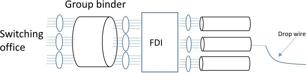
The wireline that connects a house to a switching office (class 5 switching center of a telecommunication company) is called local loop, last mile, or subscriber loop. The local loop is usually made of copper wires. These copper wires may have gauges in the range of 19 AWG to 26 AWG. They are insulated using Polyethylene dielectric. A typical local loop with multiple feeder cables coming from a switching office is shown in Fig. 1. A feeder cable is made of up to 50 binder groups where each binder group has 20 or 50 pairs of wires. A feeder cable is usually divided into some distribution cables at a location called a feeder distribution interface (FDI). These distribution cables are divided among many drop wires which goes to customer houses.
The distance from a switching office to the customer houses is in 4 km range. All signals in the local loop are differential. This means that the absolute value of the amplitude of the current in both wires are the same, but opposite current runs in each wire. Measuring the resistance of the local loop at the switching office when wires are shorted at the customer side should not be more than 1500 ohm. It would be good to make the gauge of wires based on the length of the local loop.
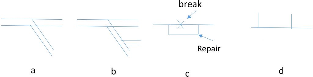
A local loop may have bridge taps, which are open-circuited wires that are connected to the local loop wires. Bridge taps are usually created due to problems with the repair and maintenance of the local loop, or as a result of different practices in installation of the local loop or house wiring. For example, in a local loop system, several customers may have shared a line in the past. Later when each customer got its own line, the shared line might be left unterminated which acts as an open-circuit stub still connected to the shared line as shown in Figs. 2a and 2b. The bridge tap can also be created after a repair to the line. If a pair breaks somewhere inside the cable as shown in Fig 2c, the repair person, may simply slice in another pair without disconnecting the broken section. This results in creation of two bridge taps connected to the loop in use as shown in Fig. 2d Bridge taps also exist as a result of existence of multiple telephone outlets inside customer houses. The most common wiring inside a house is a tree. All the branches that are not terminated or terminated in on-hook telephone make short bridges taps.
The Unshielded Twisted Pair (UTP) used in local loop would reduce the voice quality on long loops. To solve this problem, a 88mH loading coil inserted every 2km. Even though this method increase the quality of the voice, it greatly degrade response beyond 4 KHz. To use local loop for ADSL or VDSL technology, these loading coils has been removed or short out.
To protect terminal equipment, all Local loops have to be transformer-coupled. It is clear that large common-mode voltages on the loop might damage terminal equipment. Also to protect the equipment from the DC current, the equipment have to be coupled using capacitor. The transformer inductor and the capacitor create a high pass filter at each end.
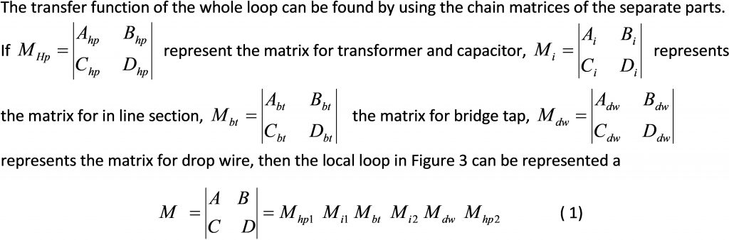
In general a local loop is made of transformer & capacitor, in-line sections, bridge taps, a drop wire and capacitor and transformer at both sides. Fig. 3 shows an example of a local loop that has a bridge tap, and two in line sections, a drop wire section and a transformer and a capacitor in each side.
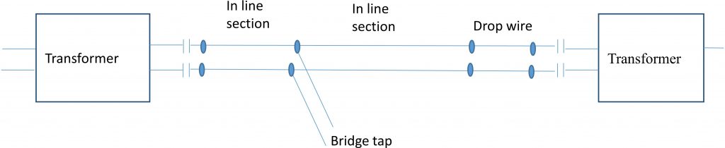
The local loop can be considered as shown In Fig 4, while V1 is connected to Vs through the resistance R1 and V2 is connected to R2 .
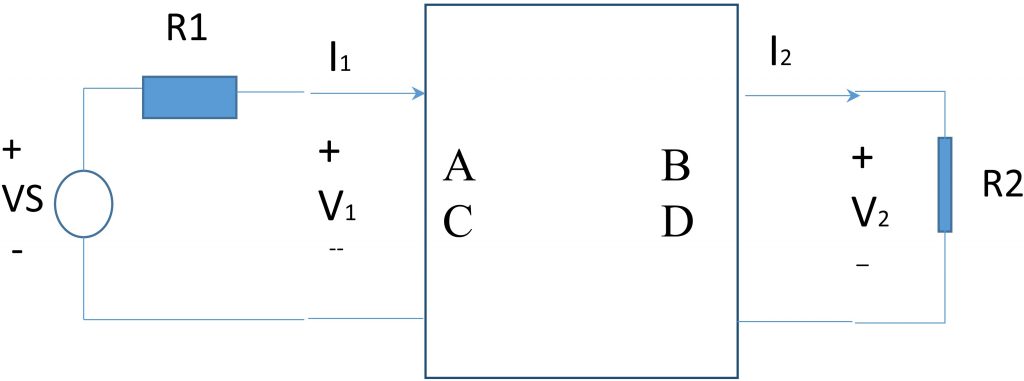
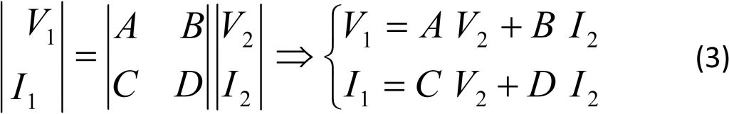
Since V1-Vs= R1 I1 , then it can be expressed that V1=Vs-R1 (C V2+D I2) . On the other hand, I2=V2/R2 . But putting V1 and I2 , in the first equation in (2), then
Vs- R1 (C V2+D V2/R2)=A V2 +B V2/R2 (3)
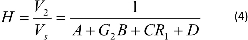
Therefore, the transfer function of the loop can be calculated as
In here, we will show the matrices for high pass filters, inline section, bridge tap and drop wire.
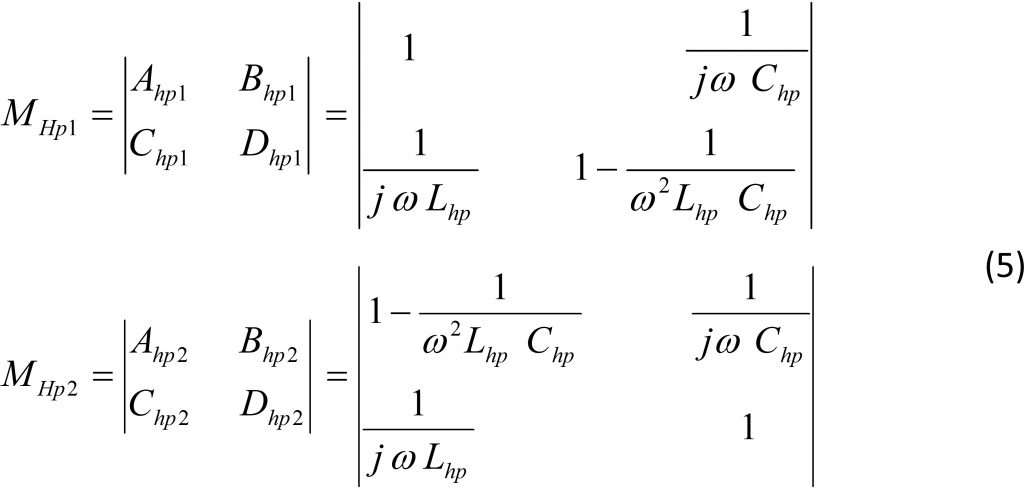
Transformer and capacitor matrix
If Chp is the capacitor and Lhp is the transformer inductor, then the matrices for transformer and capacitor at the CO side and customer side respectively will be
In line section or drop wire matrices
If R, G, L, and C are the parameters of UTP cable used for in line section or drop wire, then the matrix for these section can be expressed as
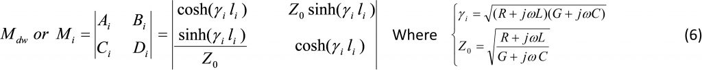
Ii represents the length in Kft. The value of the capacitor is 15.7 nF per Kft or 50pF per meter. The value of G is negligible=0.0001. C is essentially constant with frequency. The value of L and R will change with frequency as shown below.
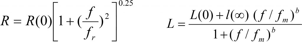
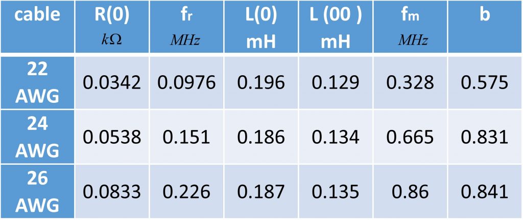
The values of R(0), fr, L(0), L(), fm, and b for different types of UTP cable is listed in the Table 1. This table is arranged per kft.
Table 1
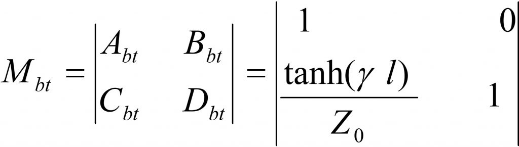
Bridge tap matrix
If R, G, L, and C are the parameters of UTP cable used for simple bridge tap (as shown in Fig. 2a), then the matrix for these section can be expressed as below. For double bridge taps (as shown in Fig. 2b) the formula is more complex.
Procedure
- Plot and compare the value of R and L for a UTP cable of 22 AWG, 24 AWG and 26 AWG in terms of frequencies.
- Write a Matlab function that receive the length and AWG of the UTP cable, the frequency of input signal, and calculate the A B C D parameters of inline section.
- Write a Matlab function that receive the length and AWG of the UTP cable, the frequency of input signal, and calculate the A B C D parameters of bridge tap.
- Calculate A B C D parameters for the local loop shown in Fig. 3, at frequency of 500 KHz without any transformer and capacitor. Considering that the first in-line section uses 9 kft of a 26 AWG cable and second in-line section is 1.5 kft of 24AWG cable, the drop wire is 50 ft of 22 AWG cable and the simple bridge tap has a length of 0.5 kft and it is a 24 AWG UTP cable.
- Plot the frequency response of the local loop in (d), from 0 to 1.2 MHz. Assume R1=R2=100Ω.
- Plot the frequency response of (d) if there was no bridge tap and compare your result with (e)
- Do you think that calculating the frequency response as you did in step (e), by considering the transformer and capacitor, would change the result or not. Explain your reason.
