Chapter 8. Geological Structures, Part B: Folds, Faults, and Unconformities
Overview of Folds, Faults, and Unconformities
Stress and Strain
Rocks change as they experience stress, defined as a force applied to a given area. Because stress is a function of area, changing the area over which a force is applied will change the resulting stress. For example, imagine the stress that is created at the tip of the heel of a high heeled shoe and compare it to the bottom of an athletic shoe. In the high heeled shoe heel, the area is very small, so much stress is concentrated at that point. The stress is more spread out in an athletic shoe. If stress is not concentrated at one point in a rock, the rock is less likely to break or bend because of that stress.
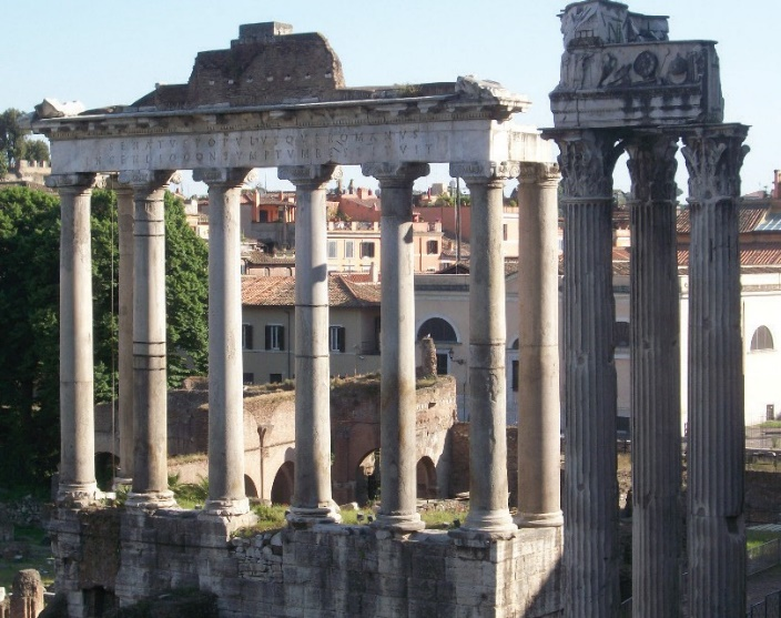
There are three main types of stress: compression, tension, and shear. When compressional forces are at work, rocks are pushed together. Tensional forces operate when rocks pull away from each other. Simple shear force is created when rocks move horizontally past each other in opposite directions. Rocks can withstand much more compressional stress than tensional stress, as is apparent in some aspects of classical architecture (Figure 8.1).
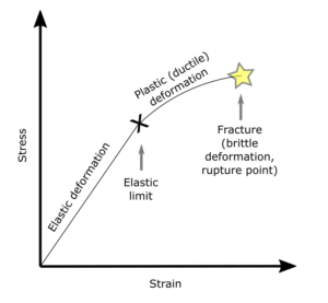
Applying stress to a rock can create deformation in that rock, known as strain. Initially, as rocks are subjected to increased stress, they behave in an elastic manner, meaning that once the stress is removed, they will return to their original shape (the first part of the curve in Figure 8.2). Deformation is elastic until the rocks reach their elastic limit (point X on Figure 8.2), at which point the rock will begin to deform plastically. Plastic deformation means that the deformation does not go away when stress is removed. It may lead to the rocks bending into folds, or if too much strain accumulates, the rocks may fracture. Deformation that does not involve a rock breaking is called ductile deformation. Deformation that results in breaking is called brittle deformation.
The deformation that results from applied stress depends on many factors, including the type of stress, the type of rock, pressure and temperature conditions, and how rapidly the stress is applied. Tension is more likely to cause brittle deformation than compression. Rocks at higher pressures and temperatures deeper within the crust are more likely to undergo ductile deformation. Sudden and rapid application of stress is more likely to produce brittle deformation.
Folds: Geologic Structures Formed by Ductile Deformation
Folds are geologic structures created by ductile (plastic) deformation of Earth’s crust. To demonstrate how folds are generated, take a piece of paper and hold it up with a hand on each end. Apply compressional forces by push the ends towards each other. You have just created a fold. Depending upon how your paper moved, you created one of the three main fold types: a monocline, anticline, or syncline (Figure 8.3).
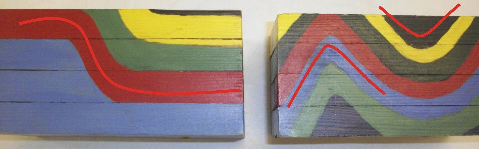
A monocline is a simple fold structure that consists of a bend in otherwise horizontal rock layers. Anticlines and synclines are more common than monoclines. An anticline fold is convex up: the layered strata dip away from the center of the fold. If you drew a line across it, the anticline would resemble a capital letter “A.” A syncline resembles a “U.” It is a concave upward fold in which the layered strata dip toward the center of the fold.
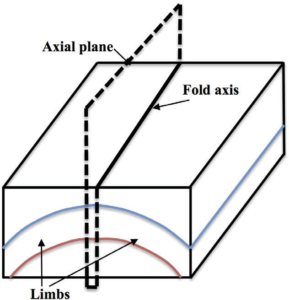
Folds have three main parts (Figure 8.4). The fold axis (also known as the hinge line), is the line that runs along the nose of the fold (where the bend is the tightest). The axial plane is an imaginary surface that contains the fold axis and generally splits the fold into symmetrical halves. A fold’s sides are called limbs, and are on either side of the fold axis.
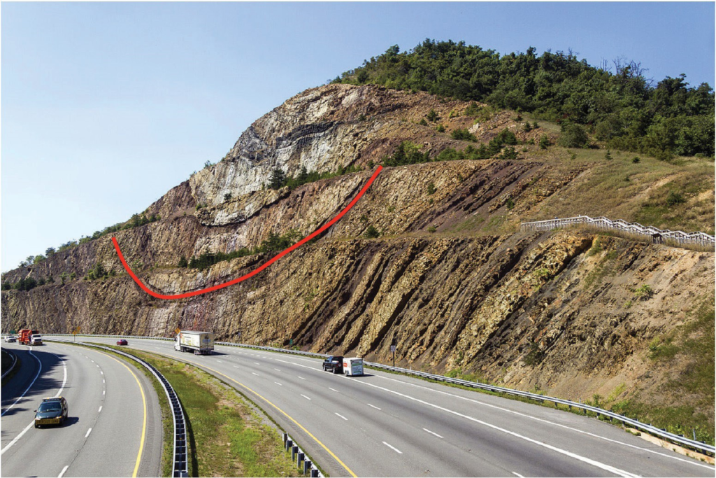
Although anticlines are hill-shaped, and synclines are valley-shaped, they may not show that way in the topography of a region. What’s more important is how easily the different rock layers making up the fold will weather. The fold in Figure 8.5 is a syncline, but the rock layers in the middle are resistant to weathering, forming a hill shape instead of a valley.
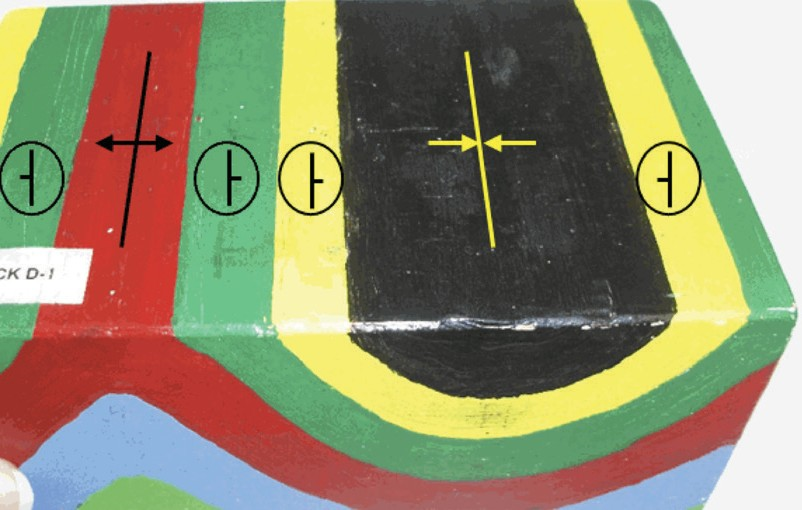
Depending on how folds are oriented, the map view might look nothing like folded layers. If the axis of a fold is horizontal, then the map view of a flat surface will show a pattern of repeating linear beds (Figure 8.6). One way to tell what kind of fold is present—monocline, syncline, or anticline—is to determine the strike and dip of the beds. Figure 8.6 shows an anticline (left) and a syncline (right) with their fold axes marked in with straight lines. Notice that strike and dip symbols have the dip pointing away from the axis of the anticline, and toward the axis of the syncline. (Disregard the circles around the strike and dip symbols.) The arrows on either side of the fold axes indicate the dip direction. The combination of fold axis and arrow pair are used to label folds on geological maps.
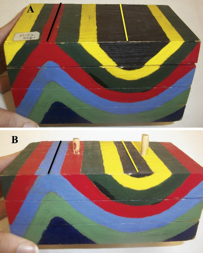
When rocks are folded and exposed at Earth’s surface, erosion exposes beds in ways that create particular patterns (FIgure 8.7). Not only do layers appear to repeat, but they repeat symmetrically on either side of the fold axis. In addition, the relative ages of the beds follow a particular pattern depending on whether the fold is an anticline or a syncline. In an anticline, the oldest rocks are exposed along the fold axis (or core) of the fold. In a syncline, the youngest rocks exposed along the fold axis.
Plunging Folds
So far, we’ve studied folds with a horizontal fold axis. These folds are shaped like ripples in water, with the axes of the folds lying in the tops and bottoms of the ripples. But some folds have a fold axis that is tilted downward. These are called plunging folds. Let’s explore what beds might look like for a plunging fold. Take a piece of paper and create a fold by compressing the paper from either side. Tip the piece of paper along the fold axis so that the axis is no longer horizontal, and instead tilts downward in one direction. You have now created a plunging fold.
Plunging folds create a V-shaped pattern when they intersect a horizontal surface (Figures 8.8, 8.9). The same pattern of oldest and youngest layers occurs with plunging folds as with horizontal ones, except with a V-shape: in a plunging anticline, the oldest strata can be found at the center of the V, and the V points in the direction of the plunge of the fold axis. In a syncline, the youngest strata are found at the center of the V, and the V points in the opposite direction of the plunge of the fold axis.
Domes and Basins
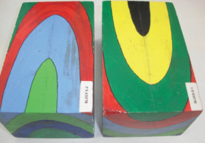
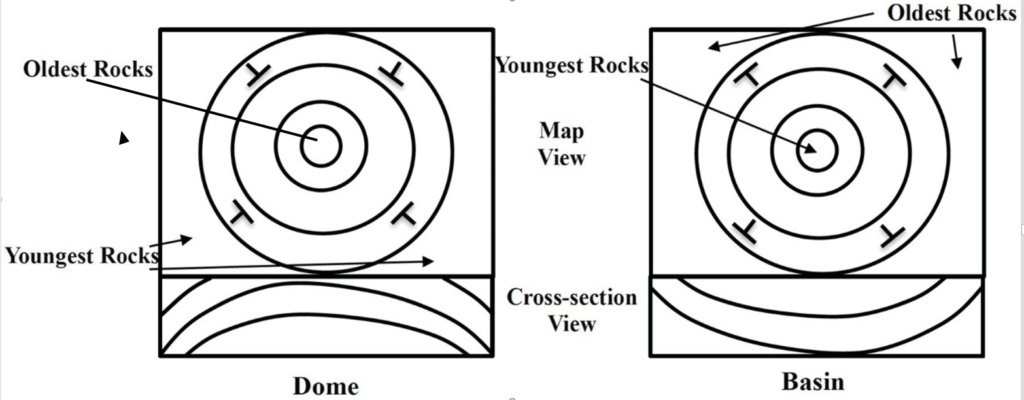
Domes and basins are somewhat similar to anticlines and synclines, in the sense of being the circular (or elliptical) equivalent of these folds. A dome is an upwarping of Earth’s crust, which is similar to an anticline in terms of the age relationships of the rocks (Figure 8.10, left). A basin is an area where the rocks have been warped downwards towards the center, with age relationships being similar to a syncline (Figure 8.10, right). The key to identifying these structures is similar to identifying folds. In a dome, the oldest rocks are exposed at the center, and rocks dip away from this central point. In a basin, the youngest rocks are in the center, and the rocks dip inward towards the center.
Summary
They key characteristics to remember about folds and basins when working with maps and cross-sections are the following:
Anticlines, plunging anticlines, and domes: The oldest beds are in the middle because the middles are pushed up. Beds dip away from the middle. The V of the plunging anticline points in the plunge direction.
Synclines, plunging synclines, and basins: The youngest beds are in the middle because the middles are pushed down. Beds dip toward the middle. The V of the plunging anticline points opposite the plunge direction.
Faults: Geologic Structures Formed by Brittle Deformation
When rocks undergo brittle deformation, they fracture. If no appreciable lateral displacement has occurred along fractures, they are called joints. If lateral displacement occurs (i.e., rocks on one side of the fracture move relative to rocks on the other side), these fractures are referred to as faults.
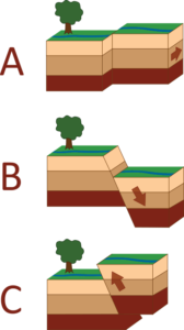
Faults are broadly classified into two categories depending on how the motion happens. If the rocks are shifting sideways on either side of the fault (Figure 8.11 A), the fault is called a strike-slip fault. If the rocks on either side are moving up or down the fault plane (Figure 8.11 B, C), it is a dip-slip fault.
Dip-Slip Faults
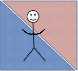
The two masses of rock that are cut by a fault are called fault blocks, and the each fault block gets a special name depending on whether it is above or below the fault. The hanging wall is the block located above the fault plane, and the footwall is the block located below the fault plane. The term hanging wall comes from the idea that if a miner were climbing along the fault plane, they would be able to hang their lantern above their head from the hanging wall. For beginners, it can be helpful to draw a stick figure straight up and down across a cross-section of the fault plane (FIgure 8.12). The head of the stick figure will be on the hanging wall and the feet of the stick figure will be on the foot wall.
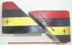
Dip-slip faults are further classified according to how the hanging wall moves relative to the footwall. When extensional (tension) forces are applied to the fault blocks (e.g., where tectonic plates are pulling apart, such as along the Mid-Atlantic Ridge), the hanging wall block will move down with respect to the foot wall block. This creates a normal fault (Figure 8.13). An easy way to remember that the hanging wall drops in a normal fault is to use the mnemonic “It’s normal to fall downhill”. Normal faults cause the crust to be lengthened (stretched apart) and thinned.
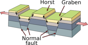
Tensional forces acting over a wider region can produce normal faults that result in landforms known as horst and graben structures (Figure 8.14). In horst and graben topography, the graben is the crustal block that drops down relative to the crust around it. The graben is surrounded by two horsts; these are relatively uplifted crustal blocks. This terrain is typical of the Basin and Range province in the western United States.
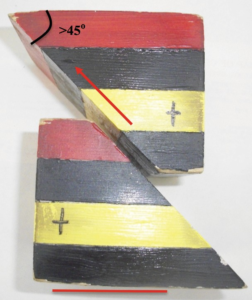
When compressional forces are applied to the fault blocks (e.g., along a convergent plate boundary), the hanging wall block will move up relative to the footwall block, creating a reverse fault (Figure 8.15). This causes the crust to shorten laterally but thicken vertically. If the reverse fault happens on a fault plane dipping at less than 30°, then it is a special type of reverse fault called a thrust fault.
Summary
The key differences between normal and reverse faults are summarized below:
Table 8.1
| Fault type | Type of force | Direction* | Length of block | Crustal thickening or thinning |
| Normal | Extensional | Down | Lengthened | thinning |
| Reverse | Compressional | Up | Shortened | thickening |
* hanging wall block movement relative to foot wall block
Strike-Slip Faults
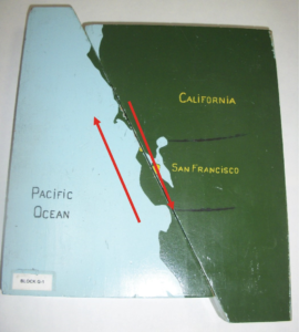
In a strike-slip fault, movement is horizontal along the fault plane. It happens along the strike of the fault plane, hence the name. There is no vertical motion involved. Purely strike-slip faults usually have a vertical fault plane. The movement of blocks on opposite sides of a strike-slip fault sliding past each other is driven by shear forces acting on the fault blocks on either side of the fault. The classic example of a strike-slip fault is the San Andreas Fault in California, USA (Figure 8.16).
Strike-slip faults can be furthered classified as right-lateral or left-lateral strike-slip faults. To determine whether a fault is left- or right-lateral, use the following test: imagine an observer standing on one side of the fault looking across at the opposite fault block. If the fault block on the opposite side of the fault appears to have moved right relative to the observer, it is right-lateral; if it appears to have moved left, it is left-lateral.
Unconformities on Geological Maps
Unconformities mark gaps in the geological record where a rock unit is overlain by another rock unit that was deposited substantially later in time. There are three main types of unconformities:
1. Disconformity: The gap in time is between parallel sedimentary rock layers. The gap was caused either by erosion or non-deposition during the time period.
2. Nonconformity: A gap in time between crystalline basement rock formation (i.e. igneous and metamorphic) and the sedimentary rocks located immediately upon the basement rock. Nonconformities commonly span vast amounts of time, up to billions of years.
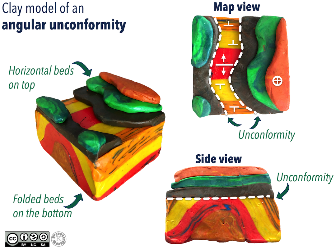
3. Angular unconformity: A gap in time between sedimentary rock layers, but the older rocks were tilted or folded so they have a different orientation than the rocks above.
Identifying unconformities on geological maps can be difficult. Disconformities are almost impossible to locate, unless you know the ages of the different layers of rocks. You might be able to find a disconformity by looking at the ages of rocks in the map legend, and trying to spot instances of missing time.
Nonconformities can also be tricky, because intrusive contacts can be mistaken for them. But if you find sedimentary rocks that are located next to large swaths of igneous and metamorphic rocks, you have likely found a nonconformity.
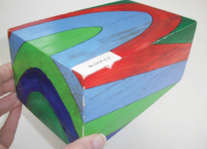
Angular unconformities can be very simple to locate on geological maps and cross-sections (or in clay models, like the one in Figure 8.17). Since overlying sedimentary rocks were deposited upon lower tilted or folded units, these overlying rocks will drape on top of the lower units. If you follow along the contacts of the lower units, you will find that they all truncate against the angular unconformity.
Test Your Understanding of Unconformities
Figure 8.18 shows examples of nonconformities and angular unconformities. The sedimentary rocks of the Athabasca Basin, and the sedimentary rocks of the western Canadian Sedimentary Basin and Williston Basin all rest nonconformably on the metamorphic basement rocks of the Canadian Shield, with gaps in the rock record ranging from 1 – 2.7 Ga. The boundary between the sedimentary rocks of the Western Canadian Sedimentary Basin and the Williston Basin are an example of an angular unconformity, and represents a 300 million year gap in the rock record.
Folds, Faults, and Unconformities on Geological Maps and Cross-Sections
On a geological map, you can spot more complex structures in the following ways:
Folds: Horizontal folds will appear as repeating bands of beds that are arranged in mirror-image on either side of the fold axis. Plunging folds are the easiest to spot, because they make a wavy pattern on the surface of the map. You can tell an anticline from a syncline by looking for strike and dip symbols, looking for the map symbols for those types of folds, or simply noticing whether the beds are older toward the centre of the fault (an anticline), or going away from the axis (a syncline).
Unconformities: You may see groups of sedimentary rocks with a different orientation than those below. This might be obvious from the shape of the beds on the map, but you might also need to look more carefully at strike and dip symbols to see a difference.
Faults: Offset beds, or beds that repeat are signs that a fault might be present. Beds that repeat because of a fault are different from repeating caused by folding. The faulted beds are always in the same order, whereas the folded beds will repeat as mirror-images of each other. Beds that appear offset are another indication that a fault has occurred. Note that if a dip-slip fault occurs in dipping beds, the fault can appear to have a strike-slip component after erosion occurs, even though the motion has been entirely up-and-down.
Principle of Lateral Continuity
In the previous chapter we discussed the principle of superposition (the oldest sedimentary bed will be on the bottom), original horizontality (sedimentary beds are deposited horizontally) and cross-cutting relationships (if one structure cuts across another one, the structure being cut is older). The principle of horizontality comes in handy for interpreting folded beds, because it means that if beds are folded or tilted, that had to happen after the beds were deposited. The principle of cross-cutting relationships will help you determine when a fault has occurred compared to other events in rocks displayed in a cross-section or on a map.
There is one more principle to keep in mind that will help you spot faults and unconformities: the principle of lateral continuity. This principle states that sedimentary beds continue laterally until they thin and pinch out. They don’t end abruptly, so if you see sedimentary layers that seem to be cut off, that could mean you’re looking at a fault or unconformity.
Block Diagrams and Cross-Sections
Test Your Understanding of Faults and Folds
Drawing Folds on Cross-sections
Advance through the slides below to see a step-by-step example of how to draw a cross-section with folded beds, a fault, and an angular unconformity.
