9 Bond Graph Models for Multi-Domain Systems
9.1 Overview
As mentioned in previous sections (see chapter 3), the universality of BG elements for application to analogous quantities is the main strength of this method for modelling and simulation of multi-domain systems. In practice, many systems are composed of multi-energy domains, e.g., an electric motor turning a mechanical shaft, a car engine generating and transferring power to the torsion shaft, a wind turbine, a robot. The BG modelling method can serve as a powerful tool for modelling these real-world systems.
In this chapter, we present several examples of multi-domain systems and build their BG models. We emphasize that the control sub-system is a major part of any engineering system. In this textbook, however, we focus on BG method and how to build BG models for systems. The full treatment of the topic of control is left for a possible future volume. For information about control theory and modelling, consult with references such as those cited as [20], [21], [30], and [31].
9.2 Example: Car Brake System
For this example we consider a car brake system as shown in Figure 9‑1. The driver applies a force on the brake pedal, which is transferred to the brake discs through the hydro-mechanical system. The process of force transfer is modelled with using several transformer elements ( ).
).
The following video shows how to build and run the model for this example in 20-sim.
The BG model for this system is shown in Figure 9‑2. For further reading, consult with the reference cited as [32].
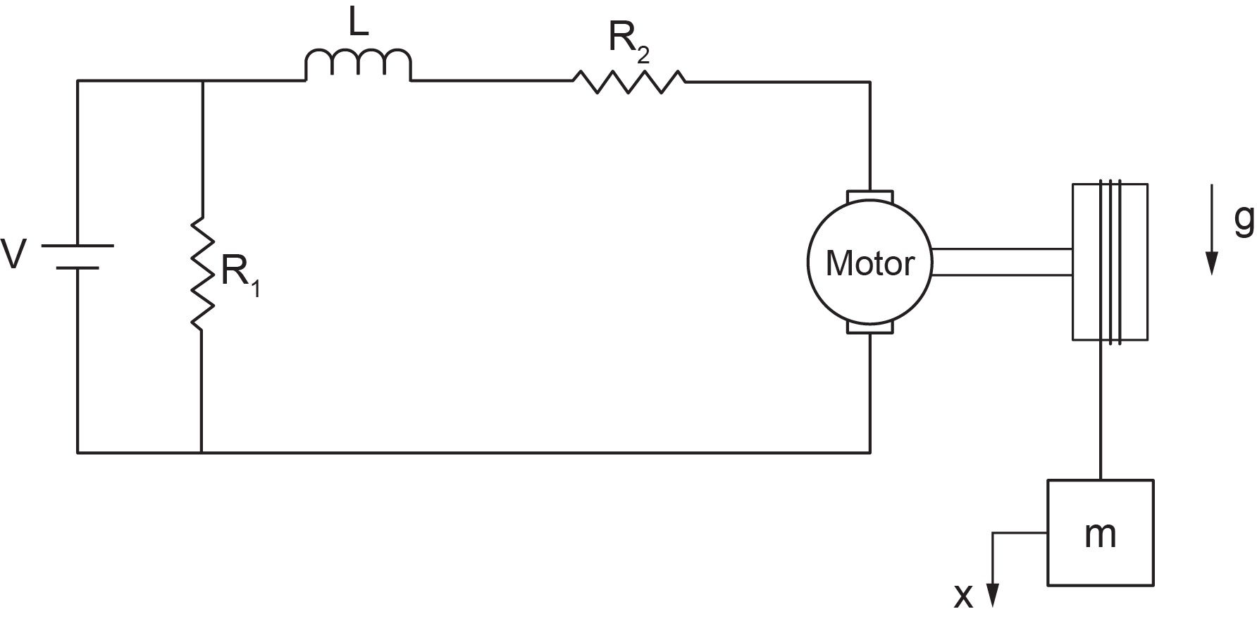
9.3 Example: Electro-mechanical Hoist System
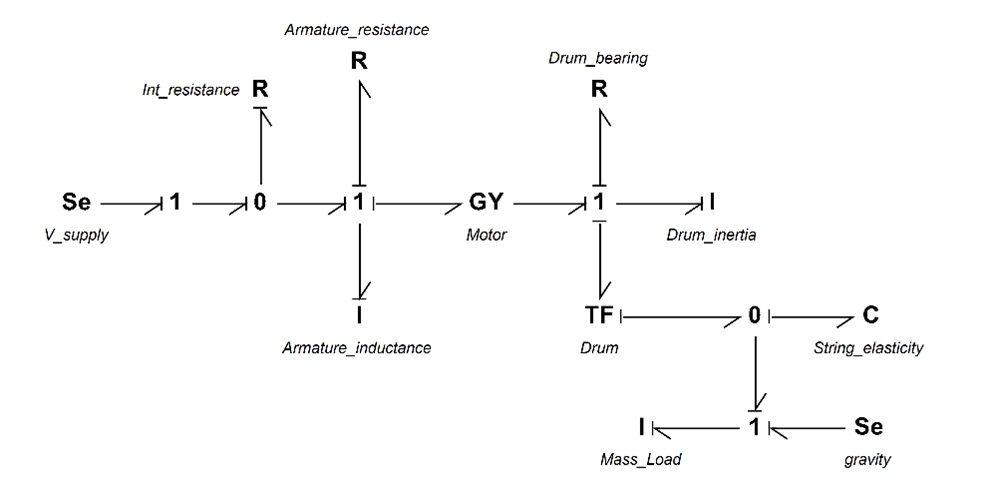
For this example, we consider an electro-mechanical hoist system as shown in Figure 9‑3. The electric motor is connected to a shaft-drum mechanical system. The load is represented by a mass connected by an elastic extensible string to the hoist drum. A gyrator ( ) and a transformer () elements are used in this model. The -element models the electric motor by transforming the motor voltage (current) to the angular velocity (torque) of the drum/shaft and the -element transforms the angular velocity of the drum to the linear velocity of the mass.
The following video shows how to build and run the model for this example in 20-sim.
Figure 9‑4 shows the BG model for this system. For further reading, consult with the references cited as [21] and [33].
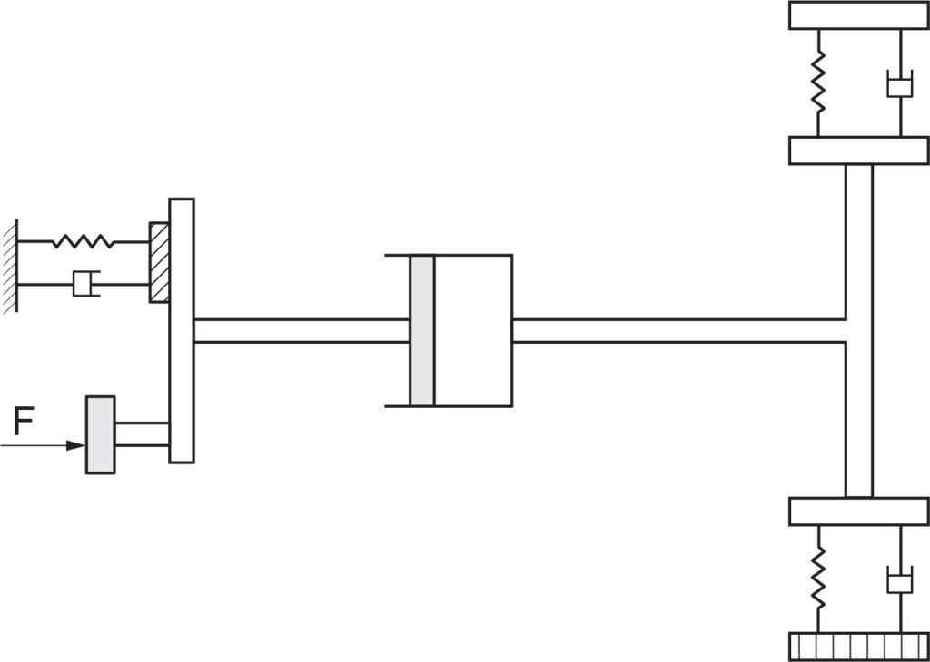
9.4 Example: Drive Shaft-Load Mechanical System
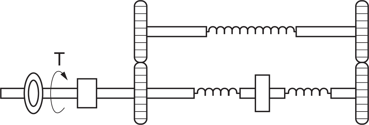
For this example, we consider a mechanical drive shaft system carrying a torsional load as shown in Figure 9‑5. The applied torque is transferred to the gear-shaft system. The load can be applied through an electric motor (not shown). This model uses several transformer elements (). The -elements exchange the angular velocity of the gears, using compatibility requirement.
The following video shows how to build and run the model for this example in 20-sim.
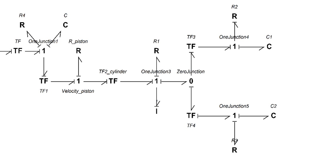
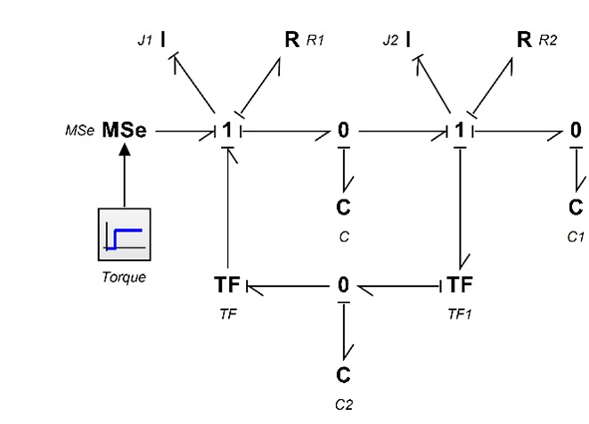
The BG model for this system is shown in Figure 9‑6. For further reading, consult with the references cited as [20] and [34].
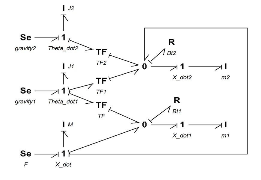
9.5 Example: Inverted Double Pendulum
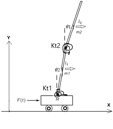
For this example, we consider an inverted double pendulum system pivoted to a moving mass,  as shown in Figure 9‑7. The rods are pinned together, and each has one rotational DOF, represented by
  and
and  . The centre of mass is located at the mid-points
  and
and  of each rod, represented by
  and
and  ; associated mass by
  and
and  ; and rotational moment of inertia by
  and
and  . The motion is measured with reference to a fixed coordinate system,
  , initially at origin. Applied force
  is exerted on mass , moving horizontally with its displacement designated by
  .
.
The coordinates of the centre of mass for the rods are given as  ,
,  , and
, and  ,
,  . Therefore, the corresponding velocities are
  ,
,  ,
,  , and
, and  . Assuming small angles, or
  and
and  , we get
  and
and

The following video shows how to build and run the model for this example in 20-sim.
Figure 9‑8 shows the BG model for this system. For further reading, consult with the references cited as [20] and [32].
Exercise Problems for Chapter 9
Exercises
- Use the BG model given in section 9.2 to complete the following:
- Build the BG model.
- Reset the causalities and manually apply them to identify the algebraic loop and related power bonds. List all the options that might exist.
- Using some typical numerical values for the car-brake system parameters, build the model and run some simulation scenarios.
- Use the BG model given in section 9.3 to complete the following:
- Build the BG model.
- Reset the causalities and manually apply them to related power bonds.
- Draw the arrows for showing the streams of flow and effort in the whole system.
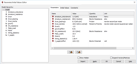
- Using some typical numerical values (as shown below) for the hoist system parameters, build the model and run some simulation scenarios. Make graphs of mass velocity and study the effects of string elasticity and drum moment of inertia using the Parameter Sweep tool in 20-sim.