5 Introduction to 20-sim Software Tool
5.1 Overview
In this chapter, we introduce the engineering software tool 20-sim, focusing on its BG modelling and simulation facilities. Originally developed in the Netherlands at the University of Twente and released in 1995, 20-sim was the first commercially released software package for bond graph modelling. 20-sim was further developed and currently is available through Controllab Products [3].
An advanced modelling and simulation software tool, 20-sim uses Microsoft Windows™ operating system. 20-sim enables users to model the behaviour of systems, such as mechanical, electrical, hydraulic, thermal, or a combination of these systems (i.e., multi-domain systems). Below is a list of 20-sim’s modelling and simulation tools. The first four items in the list are the main tools:
- bond graph
- block diagrams
- iconic diagrams
- equation models
- 3D animation
- 3D mechanics
- code generation
- controller design
- frequency and time domain
- multi-domain systems
- virtual reality: Unity Toolbox
20-sim allows users create models graphically, similar to drawing an engineering sketch. With these models you can simulate and analyze the behaviour of single-domain and multi-domain dynamic systems and create control systems. One can even generate C-code and run this code on hardware for rapid prototyping and hardware-in-the-loop (HIL) simulation.
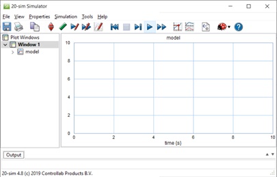
20-sim has two main window interfaces: Editor and Simulator, shown in Figure 5‑1 and Figure 5‑2, respectively. To open the Simulator window from the keyboard, select Ctrl + R. To open the Simulator window from the Editor window, choose Tools > Simulator.
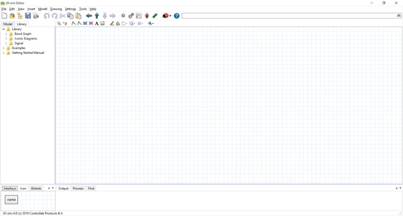
As described in the manual Getting started with 20-sim 4.8, the Editor consists of four parts:
- Model tab/Library tab: This is the part at the middle left. The Model tab shows the model hierarchy, i.e., the hierarchical composition (all the elements) of the model that is created in the Editor. The Library tab shows the 20-sim library.
- Graphical Editor/Equation Editor: This is the big white space, with or without grids, at the middle right. The Editor is used to create graphical models and enter equations.
- Output tab/Process tab/Find tab: This is the part at the bottom right. The Output tab shows the files that are opened and stored. The Process tab shows the compiler messages. The Find tab shows the search results.
- Interface tab/Icon tab: This is the part at the bottom left. The Interface tab shows the interface of a selected model. Double-click to open the Interface Editor.
- The Icon tab shows the icon of a selected model. Double-click to open the Icon Editor.
Here is a video guiding the reader through the features of 20-sim:
More information about using 20-sim is available at 20-sim webhelp and at 20-sim Help Manuals.
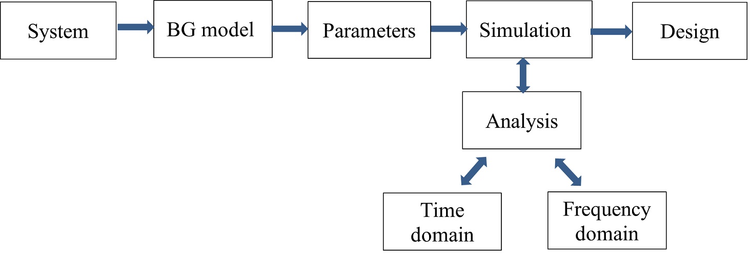
Figure 5‑3 shows the main steps for system design. In further sections, we will follow these steps with several worked-out examples to demonstrate the application of this process.
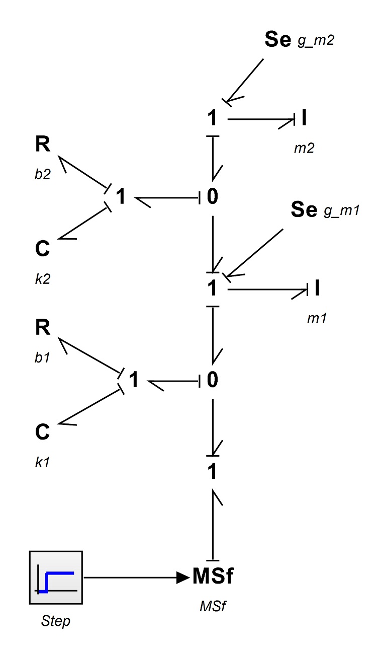
5.2 Example: BG Model for a Car Seat Mechanical System
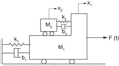
To demonstrate 20-sim application, using the data provided in Table 5‑1, we build a BG model of a car seat. The car seat system schematic is shown in Figure 5‑4. Consider the (+C) to be the sign convention for internal forces.
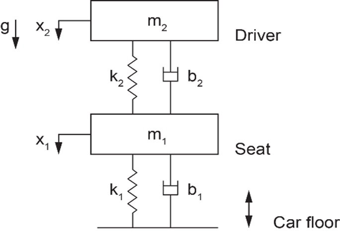
| Component/element | Value | Unit |
Mass,  |
27 | kg |
Mass,  |
80 | kg |
Spring,  |
1800 | N/m |
Spring,  |
19 x 104 | N/m |
Damper,  |
400 | N.s/m |
Damper,  |
900 | N.s/m |
Car floor speed,  |
signal | step-function |
Solution:
Here are two videos showing how to build and run the model for this example in 20-sim:
Launch 20-sim and follow the solution steps provided in the videos. Figure 5‑5 shows the resulting BG model.
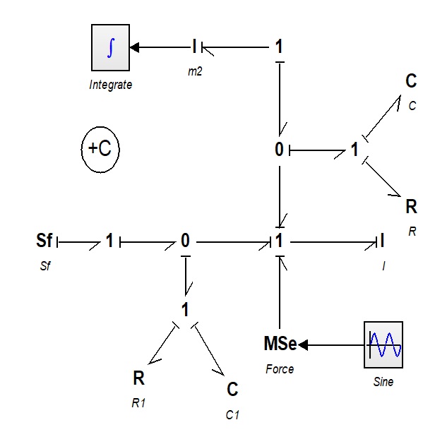
5.3 Example: BG Model for a Cart Carrying a Load
To demonstrate 20-sim, we build a BG model of a cart carrying a load. Consider the (+C) to be the sign convention for internal forces.
Table 5‑2 shows the data for the system components. Figure 5‑6 shows the cart system schematic.
| Component/element | Value | Unit |
| Mass, |
40 | kg |
| Mass, |
20 | kg |
| Spring, |
2000 | N/m |
| Spring, |
1500 | N/m |
| Damper, |
400 | N.s/m |
| Damper, |
900 | N.s/m |
Force,  |
signal | sinusoidal |
Solution:
The process for building a BG model and related simulation for this example is given through a screen recording that guides the readers through the whole process. Launch 20-sim, and to build and run the 20-sim model for this example, follow the solution steps provided in the following video:
Figure 5‑7 shows the resulting BG model.
Exercise Problems for Chapter 5
Exercises
- Familiarize yourself with the 20-sim tools and features, using the screen recording in section 5.1.
- Build the BG model using 20-sim for the example given in section 5.2 considering:.
- (+T) as the sign convention for internal forces
- (+C) as the sign convention for internal forces
Run the model for simulation and create and report typical graphs.
- Build the BG model using 20-sim for the example given in section 5.3 considering:
- (+T) as the sign convention for internal forces
- (+C) as the sign convention for internal forces
Run the model for simulation and create and report typical graphs.
