34 Introduction to Energy Balances
Learning Objectives
By the end of this section, you should be able to:
Identify relevant terms for energy balances for open and closed systems
Use thermodynamic data tables to identify enthalpy, internal energy, and other thermodynamic properties using system temperatures and pressures
Solve energy balance problems using thermodynamic data
Forms of Energy
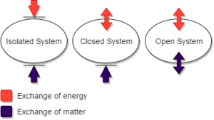
Systems are typically divided into three main categories depending on how the system interacts with its surroundings:
- Isolated - No energy or mass transfer between system and surroundings, energy may change form within the system
- Closed - Energy, but no mass transfer between system and surroundings
- Open - Energy and mass transfer between systems and surroundings, typically use a [latex]\dot{}[/latex] with quantities that change over time in these open systems to denote the flow rate of energy or mass.
Kinetic Energy - [latex]E_{k}[/latex]
Kinetic Energy is energy associated with motion, which can be described as translational or rotational energy.
[latex]E_{k} = \frac{1}{2} mu^{2}[/latex]
[latex]\dot{E}_{k} = \frac{1}{2} \dot{m} u^{2}[/latex]
where:
[latex]m[/latex] is mass
[latex]u[/latex] is velocity relative to a reference. Generally we refer to earth's surface as stationary.
Potential Energy - [latex]E_{p}[/latex]
Potential energy can be described as energy present due to position in a field, such as gravitational position or magnetic position
Usually for chemical processes, we consider the potential energy change due to the gravitational position of the process equipments.
[latex]E_{p} = m g z[/latex]
[latex]\dot{E}_{p} = \dot{m} g z[/latex]
[latex]\Delta E_{p} = E_{p2} - E_{p1} = m g (z_{2} - z_{1})[/latex]
where:
[latex]m[/latex] is mass
[latex]g[/latex] is the gravitational acceleration (approximately 9.8 [latex]m/s^{2}[/latex])
[latex]z[/latex] is the height about the point of reference
Internal Energy - [latex]U[/latex]
Internal energy can be described as all other energy present in a system, including motion, and molecular interaction.
Heat - [latex]Q[/latex]
- Heat is the energy flow due to temperature difference
- Heat flows from higher temperatures to lower temperatures
- Heat is generally defined as positive when it is transferred from the surroundings to the system
Work - [latex]W[/latex]
- Work is energy resulting from driving forces (not temperature) such as force, torque, or voltage
- We will define work as positive when work is done by the surroundings on the system, this is a typical convention in chemistry. With this convention, we would write "Q + W" in our energy balances. However, historically work has also been defined in physics as positive when work is done by the system on the surroundings. In this other case, the energy balance would be written with "Q - W". Both can be used and this is accounted for in the sign we use in front of the work term in energy balances.
Energy Transfer in Closed Systems
Closed systems are defined as systems with no mass transfer across the system's boundaries. All the energy forms described above are applicable to closed systems.
Exercise: Energy Balance Sign Conventions
Consider a system that consists of a stirred tank reactor where an exothermic reaction is taking place, where an external motor is mixing the contents in the reactors. What are the signs of [latex]Q[/latex] and [latex]W[/latex] for this system?
Solution
For an external motor that is mixing the contents in the reactor, work is being done by the surroundings on the system. Therefore, [latex]W[/latex] is positive.
Energy Balances on Closed Systems
Energy in closed systems follows the Law of Conservation of Energy
[latex]Accumulation = Input - Output[/latex]
In terms of general energy:
[latex]E_{system,final} - E_{system,initial} = E_{system,transferred}[/latex]
The initial energy in the system can be defined as:
[latex]U_{i} + E_{k,i} + E_{p,i}[/latex]
The final energy in the system can be defined as:
[latex]U_{f} + E_{k,f} + E_{p,f}[/latex]
The energy transfer of the system can be defined as:
[latex]Q + W[/latex]
This yields the following closed system energy balance, defined as
the First Law of Thermodynamics:[latex](U_{f} - U_{i}) + (E_{k,f} - E_{k,i}) + (E_{p,f} - E_{p,i}) = Q + W[/latex]
[latex]\Delta U + \Delta E_{k} + \Delta E_{p} = Q + W[/latex] Assumptions made by the First Law of Thermodynamics
- If no acceleration exists in the system, the change in the kinetic energy term will be 0, and can be ommitted from the balance
- If no change in height (or other fields) exist in the system, the change in the potential energy term will be 0, and can be ommitted from the balance
- Internal energy depends on chemical composition, state (solid, liquid, or gas) and temperature; Pressure's effect is negligible.
- If the system has the same temperature as its surroundings or is adiabatic, the heat term will be 0, and can be ommitted from the balance
- If there are no moving parts, electrical currents, or radiation in the system, the work term will be 0 and can be omitted from the balance
Work in Open Systems
Open Systems:
Open systems are defined as systems where both mass and energy cross the system's boundaries.
Two types of work are typically observed in these systems:
- Shaft Work - [latex]W_{s}[/latex]or [latex]\dot{W}_{s}[/latex]
Shaft work is work done on process fluid by a moving part, such as a pump, rotor, or a stirrer. - Flow Work - [latex]W_{fl}[/latex] or [latex]\dot{W}_{fl}[/latex]
Flow work is work done on process fluid (inlet minus outlet). For the work flow in, the surroundings do work on the system, therefore it is positive. For the work flow out, the system does work on the surroundings, therefore it is negative.
[latex]\dot{W}_{fl} = \dot{W}_{fl-in} - \dot{W}_{fl-out} = P_{in}\dot{V}_{in} - P_{out}\dot{V}_{out}[/latex]
Steady-State Open-System Energy Balance
Energy Conservation for a Steady-State System
For stream 'j' in a system:
[latex]\Sigma_{in} \dot{E}_{j} + \dot{Q} + \dot{W} = \Sigma_{out} \dot{E}_{j}[/latex]
Rearranging the energy terms, we get:
[latex]\dot{Q} + \dot{W} = \Sigma_{out} \dot{E}_{j} - \Sigma_{in} \dot{E}_{j}[/latex]
Example: Energy Flow in a System
Consider the following system:
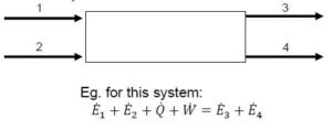
There are 2 streams with energy entering the system (streams 1 and 2), and 2 streams with energy exiting the system (streams 3 and 4).
For this system:
[latex]\dot{E}_{1} + \dot{E}_{2} + \dot{Q} + \dot{W} = \dot{E}_{3} + \dot{E}_{4}[/latex]
Recall the three forms of energy:
[latex]\dot{E}_{j} = \dot{U}_{j} + \dot{E}_{k,j} + \dot{E}_{p,j}[/latex]
Each energy flow term can be further separated into: [latex]\dot{U}_{j} = \dot{m} * \hat{U}_{j}[/latex]
Specific Property "[latex]\hat{ }[/latex]" : This denotes an intensive property obtained by dividing an extensive property by a total amount of flow rate (can be total number of moles or total mass)
[latex]\hat{V} = \frac{V}{n}[/latex]
or
[latex]\hat{U}=\frac{\dot{U}}{\dot{m}}[/latex]
Combining all these terms:
[latex]\dot{Q} + \dot{W} = \Sigma_{out} \dot{m}_{j} * (\hat{U}_{j} + \hat{E}_{k,j} + \hat{E}_{p,j}) - \Sigma_{in} \dot{m}_{j} * (\hat{U}_{j} + \hat{E}_{k,j} + \hat{E}_{p,j})[/latex]
Recall the work terms expansion:
[latex]\dot{W} = \dot{W}_{fl} + \dot{W}_s[/latex]
where flow work is dependant on system pressure and volume
[latex]\dot{W}_{fl} = \Sigma_{in} \dot{m}_{j} P_{j} \hat{V}_{j} - \Sigma_{out} \dot{m}_{j} P_{j} \hat{V}_{j}[/latex]
Now we have:
[latex]\dot{Q} + \dot{W}_{s} = \Sigma_{out} \dot{m}_{j} * (\hat{U}_{j} + P_{j} \hat{V}_{j} + \hat{E}_{k,j} + \hat{E}_{p,j}) - \Sigma_{in} \dot{m}_{j}*(\hat{U}_{j} + P_{j}\hat{V}_{j} + \hat{E}_{k,j} + \hat{E}_{p,j})[/latex]
Because [latex]\hat{U} + P\hat{V}[/latex] usually appear together in the energy balances, we define them to be "enthalpy" ([latex]\hat{H}[/latex]):
[latex]\hat{H} = \hat{U} + P\hat{V}[/latex]
where [latex]\hat{U}[/latex] is the internal energy and [latex]P\hat{V}[/latex] is the flow work
The following terms are defined:
- [latex]\Delta\dot{H} = \Sigma_{out}\dot{m}_{j}*\hat{H}_{j} - \Sigma_{in}\dot{m}_{j}*\hat{H}_{j}[/latex]
- [latex]\Delta\dot{E}_{k} = \Sigma_{out}\dot{m}_{j}*\hat{E}_{k,j} - \Sigma_{in}\dot{m}_{j}*\hat{E}_{k,j}[/latex]
- [latex]\Delta\dot{E}_{p} = \Sigma_{out}\dot{m}_{j}*\hat{E}_{p,j} - \Sigma_{in}\dot{m}_{j}*\hat{E}_{p,j}[/latex]
Finally, an open system steady-state energy balance is defined:
[latex]\dot{Q} + \dot{W}_{s} = \Delta\dot{H} + \Delta\dot{E}_{k} + \Delta\dot{E}_{p}[/latex]
Exercise: Heat for an Ideal Gas
Prior to entering a furnace, air is heated from [latex]25^{\circ}C[/latex] to [latex]150^{\circ}C[/latex] and the change in specific enthalpy for the whole heating process is 3640 J/mol. The flow rate of air at the outlet of the heater is [latex]1.5 m^3/min[/latex] and the air pressure at this point is 150 kPa absolute.
Calculate the heat needed for the process in kW. Assume the ideal gas behavior and that kinetic and potential energy changes from the heater inlet to the outlet are negligible.
Solution
Step 1: Calculate the molar flowrate using the ideal gas law.
\begin{align*}
\dot{n} & = \frac{1.5m^{3}}{min}*\frac{273K}{150+273K}*\frac{150kPa}{101.3kPa}*\frac{1mol}{22.4L}*\frac{10^{3}L}{1m^{3}}\\
\dot{n} & =64.0\frac{mol}{min}
\end{align*}
Step 2: Calculate the heat using the specific enthalpy. Since the potential and kinetic energy changes are zero, the following calculations are made
\begin{align*}
\dot{Q} & =\Delta\dot{H}= \dot{n}\Delta\hat{H}\\
\dot{Q} & =\frac{64.0 mol}{min}*\frac{1min}{60s}*\frac{3640J}{mol}*\frac{kW}{10^{3} J/s} \\
\dot{Q} & =3.88kW
\end{align*}
Reference States
Reference State: a substance at some pressure, temperature, and state of aggregation (solid, liquid, gas; pure or mixture).
It is much easier to estimate the energy of a system as a change from a reference state rather than the absolute energy.
Exercise: Cooling in a Heat Exchanger
Water is used to cool a liquid in a heat exchanger. Water enters the heat exchanger at [latex]10^{\circ}C[/latex] and exits at [latex]100^{\circ}C[/latex]. Using the table below, find the change in enthalpy of water in its liquid state.
| Entry # | [latex]T (^{\circ}C)[/latex] | [latex]\hat{H}_{L} (\frac{kJ}{kg})[/latex] |
| 1 | 5 | 21.02 |
| 2 | 10 | 42.02 |
| 3 | 100 | 419.17 |
Solution
Step 1: Determine which reference state you are going to use. In this case, we are using [latex]10^{\circ}C[/latex] as the reference state.
[latex]\Delta\hat{H} = \hat{H}_{100^{\circ}C} - \hat{H}_{10^{\circ}C}[/latex]
Step 2: Find the change in enthalpy by taking the difference of the system's specific enthalpies at different temperatures.
\begin{align*}
\Delta\hat{H} & = \hat{H}_{3} - \hat{H}_{2}\\
\Delta\hat{H} & = (419.17 - 42.02) kJ/kg\\
\Delta\hat{H} & = 377.15 kJ/kg
\end{align*}
Steam Tables
Since water is a commonly used resource in processes for heating and cooling, detailed information on its state properties at different temperatures and pressures is available.
How to Access Steam Tables on NIST
- Steam tables can be found on NIST
A. Select 'Water' from the 'Please select the species of interest:' drop-down menu
B. Choose the steam table units you'd like to work with, in step 2.
C. In Step 3, choose what kind of data you're looking to obtain. For an isothermal system, select 'Isothermal properties'. For a constant pressure system, select 'Isobaric properties'.
D. Select the desired standard state convention. This course will most likely only use the 'Default for fluid' convention.
Exercise: Steam Tables
Superheated steam at 40 bar absolute and [latex]500^{\circ}C[/latex] flowing at a rate of [latex]200 kg/min[/latex] is sent to an adiabatic turbine which expands to 5 bar. The turbine outputs [latex]1250kW[/latex]. The expanded steam is then sent to a heat exchanger where isobaric heating occurs, resulting in the stream being reheated to its initial temperature. Assume no changes in kinetic energy. Write the energy balance for the turbine and determine the outlet stream temperature.
Solution
- For water vapor at [latex]500^{\circ}C[/latex] and [latex]40 bar[/latex], the specific enthalpy is [latex]3445 \;kJ/kg[/latex]
- For water vapor at [latex]500^{\circ}C[/latex] and [latex]5 bar[/latex], the specific enthalpy is [latex]3484 \;kJ/kg[/latex]
\Delta\dot{H} &=-\dot{W}_{s}\\
\Delta\dot{H} &=\dot{m}*(\hat{H}_{2}-\hat{H}_{1})
\end{align*}
\hat{H}_{2} &=\hat{H}_{1}-\frac{\dot{W}_{s}}{\dot{m}}\\
&=\frac{3445kJ}{kg}-\frac{1250kJ}{s}*\frac{min}{200kg}*\frac{60s}{1min}\\
&=3070\frac{kJ}{kg}
\end{align*}

Feedback/Errata