8 Piping and Instrumentation Diagrams (P&IDs)
Learning Objectives
By the end of this section, you should be able to:
Understand piping and instrumentation diagrams (P&IDs)
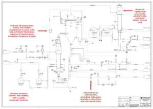
Piping and Instrumentations Diagrams (P&IDs)
P&IDs are based off of PFDs but include more specific information
P&IDs do not include:
- Operating conditions (T,P)
- Stream flows
- Equipment locations
- Supports, structures, and foundations
- Pipe routings (lengths, fittings such as elbows, but connections above a certain size are generally shown)
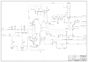
A P&ID often depicts one unit operation in thorough detail.
Exercise: P&ID Components
Consider the following diagram:
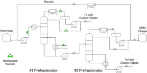
Image from Jim Cahill / CC BY-ND 2.0
What are some components that need to be added or adjusted to turn this into a P&ID?
Solution
- Equipment details
- Control instrumentation details
- Utility exit and entrance details
- Piping sizing, schedule, material of construction, and insulation
P&ID Control Symbology
You will learn more about control symbols as you go through your degree. However, below we have a brief introduction to some important symbols.
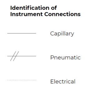
Instrument connections
- Capillary: fluid flow control
- Pneumatic: air or gas flow control
- Electrical: electrical currents controls
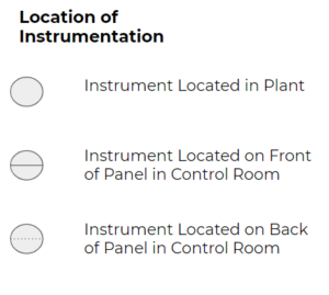
Instrument locations
- Located in plant: generally means the instrument is near what it is measuring (local), it does not go to the control room
- Front panel in control room: Control rooms used to have instrument panels and would have manual controls on the front panel facing the operators, these have been replaced largely with digital (or virtual) screens which the operators can switch between different views. You could think of the main view in these digital screens as the front panel, with the most important controls or indicators shown.
- Back panel in control room: place for instruments that are perhaps less important or do not need to be looked at frequently. In our class we won’t distinguish between these, but this is common notation you may see in P&IDs
Control panel rooms have changed quite a bit throughout the years. Below are examples of older and newer control panels.
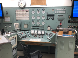
Image from XXBuilderXx / CC BY-SA
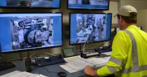
Image from PEO ACWA / CC BY 2.0
For the control symbology identification with the ‘XYY’ format:
| First Letter (X) | Second or Third Letter (Y) | |
|---|---|---|
| A | Analysis (Composition/Concentration) | Alarm |
| C | – | Control |
| F | Flowrate | – |
| H | – | High |
| I | – | Indicate |
| L | Level | Light or Low |
| P | Pressure | – |
| T | Temperature | Transmit |
Exercise: P&ID Control
What information can you derive from the following control symbol?
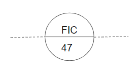
Solution
This is a flow indicator and controller, with the instrument located on the front panel of the control room with an electrical connection.
Resources for Building PFDs and P&IDs
- Visio: available through the CHBE Parallel’s Client portal, as well as the CHBE computer labs
- Visual Paradigm Online: includes specific process engineering equipment
- Draw.io
- AspenPLUS: you will use this in CHBE 376
Here is a thorough table of control symbology:
| First Letter (X) | Second or Third Letter (Y) | |
|---|---|---|
| A | Analysis | Alarm |
| B | Burner Flame | – |
| C | Conductivity | Control |
| D | Density or Specific Gravity | – |
| E | Voltage | Element |
| F | Flowrate | – |
| H | Hand (Manually Initiated) | High |
| I | Current | Indicate |
| J | Power | – |
| K | Time or Time Schedule | Control Station |
| L | Level | Light or Low |
| M | Moisture or Humidity | Middle or Intermediate |
| O | – | Orifice |
| P | Pressure or Vacuum | Point |
| Q | Quantity or Event | – |
| R | Radioactivity or Ratio | Record or Print |
| S | Speed or Frequency | Switch |
| T | Temperature | Transmit |
| V | Viscosity | Valve, Damper, or Louver |
| W | Weight | Well |
| Y | – | Relay or Compute |
| Z | Position | Drive |
Exercise: Building a PFD
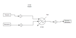
A simple system consists of two feed streams (stream 1: toluene; stream 2: benzene) that enter a heater separately and combine into 1 stream to exit. The heater uses high-pressure steam as the utility. Build a simple process flow diagram of the process described above.
Solution

Feedback/Errata