7 Process Flow Diagrams (PFDs)
Learning Objectives
By the end of this section, you should be able to:
Build process flow diagrams (PFDs)
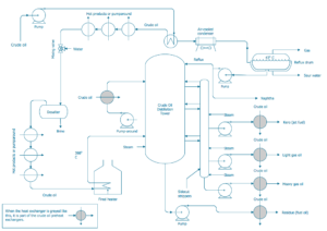
Process Flow Diagrams (PFDs)
Process flow diagrams usually include:
- Major pieces of equipment that are represented by a description and a unique equipment number and name
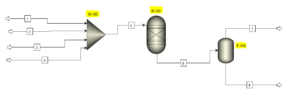
- Process flow streams that are represented by a number and sometimes include process conditions and chemical composition of each stream. This information can be shown on the PFD itself or on an accompanying flow summary table
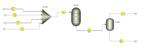
- Utility streams for major equipment
- Basic control loops that present the overarching control strategy used to operate the processes. These are generally optional, and not shown in the diagrams above.
- An equipment summary table with key details (shown later in this chapter)
PFD Equipment Numbering
This is a typical way to label a piece of equipment using its position in the process. This is not the only way to label equipment, but a very common way. We will stick with this in this class and you will likely see it very commonly.
P-101A
- First letter: equipment (P = pump)
- First number: plant section (1 = section 1 of plant)
- Last numbers: equipment number (01 = pump 1 in this section)
- Last letters: show duplicates/triplicates when two or more of the same equipment is used for the same stage of the process.
| Label | Equipment Description |
|---|---|
| C | Compressor or Turbine |
| E | Heat Exchanger |
| P | Pump |
| R | Reactor |
| T | Tower |
| TK | Storage Tank |
| V | Vessel |
PFD Utility Naming
Generally, rather than using numbers, utility streams will be labeled using a certain descriptor. These streams are labeled in this way as the same type of stream will generally have the same conditions, and so this saves repeatedly specifying these streams with numbers.
| Label | Utility Description |
|---|---|
| lps | Low-Pressure Steam (3-5 bar) |
| mps | Medium-Pressure Steam (10-15 bar) |
| hps | High-Pressure Steam (40-50 bar) |
| htm | Heat Transfer Media (organic) |
| cw | Cooling Water |
| rw | Refrigerated Water |
| rb | Refrigerated Brine |
| cs | Chemical Waste Water |
| ss | Sanitary Waste Water |
| el | Electric Heat |
| ng | Natural Gas |
| fg | Fuel Gas |
| fo | Fuel Oil |
PFD Legend
The legend should include everything to allow someone to read the PFD with no prior knowledge of the project.
PFD Summary Tables
Stream Summary Table
Certain essential information must be included in stream summary tables, this may vary slightly depending on the industry, what we will stick within this class is the following:
- Stream number
- Temperature
- Pressure
- Vapour fraction
- Total mass flowrate
- Total mole flowrate
- Individual component mole flowrates
Other information may or may not be included as well:
- Stream name
- Component mole fractions
- Component mass fractions
- Individual component mass flowrates
- Volumetric flowrates
- Significant physical properties (density, viscosity, etc.)
- Thermodynamic data (heat capacity, specific enthalpy)
| Stream Number | 1 | 2 | 3 | 4 | 5 | 6 |
|---|---|---|---|---|---|---|
| Temperature ([latex]^{\circ}C[/latex]) | 25 | 25 | 90 | 90 | 95 | 250 |
| Pressure (atm) | 1.5 | 1.5 | 1.5 | 1.5 | 30 | 20 |
| Vapor Fraction | 1.0 | 1.0 | 0.3 | 0.6 | 0.5 | 1.0 |
| Mass Flow (kg/hr) | 50,000 | 105,000 | 149,000 | 276,000 | 276,000 | 276,000 |
| Molar Flow (kmol/hr) | 1,500 | 1,500 | 1,500 | 2,600 | 1,750 | 5,000 |
| Component Molar Flow (kmol/hr) | ||||||
| Ethylene | 1,500 | 0 | 0 | 0 | 0 | 0 |
| Chlorine | 0 | 1,500 | 0 | 0 | 0 | 0 |
| 1,2-dichloroethane | 0 | 0 | 1,500 | 0 | 0 | 0 |
| Vinyl Chloride | 0 | 0 | 0 | 2,600 | 0 | 2,500 |
| Hydrogen Chloride | 0 | 0 | 0 | 0 | 1,750 | 2,500 |
Equipment Summary Table
The equipment summary table provides information on equipment specifications. These are essentially a short list of key details used for the designing or costing of equipment. Examples of what might be specified in this table for different types of equipment are shown below. As you can see, these can be quite detailed, and you'll learn more about how to specify these parameters throughout your degree.
| Equipment | Required Specification |
|---|---|
| Vessels | Height; diameter; pressure; temperature; materials of construction |
| Pumps | Flow; driver type; suction and discharge pressures; temperature; shaft power; materials of construction |
| Towers | Height; diameter; orientation; pressure; temperature; number and type of trays; height and type of packing; material of construction |
| Compressors | Inlet flow; driver type; suction and discharge pressures; temperature; shaft power; material of construction |
| Heat Exchangers | Type; area; duty; number of shell and tube passes; operating temperatures; pressures; pressure drops; material of construction |
| Fired Heaters | Type; tube pressure; tube temperature; duty; radiant heat transfer area; convective heat transfer area; material of construction |
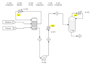
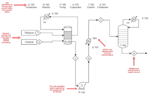
Exercise: PFD Components
Solution
- Add a legend
- Label the streams in a logical manner
- Name the equipment and utilities using the correct naming convention
- Add unit operation labels and description to the top or bottom of the PFD
- Also, consider adding stream and equipment summary tables

Feedback/Errata