4. The First Law of Thermodynamics for Closed Systems
4.4 The first law of thermodynamics for closed systems
The first law of thermodynamics is essentially an energy conservation law. Both heat and work are energy transfer mechanisms. They play an important role in the first law of thermodynamics. Table 4.4.1 summarizes the main differences between heat and work, and internal energy.
| Heat and Work | Internal Energy | |
|---|---|---|
| Characteristic | Both heat and work are energy transfer mechanisms. They are not properties of a system. | Internal energy is a property of a system. |
| Interaction with the system | Both heat and work must cross the boundary between a system and its surroundings. | A system possesses a total energy and an internal energy. |
| Magnitude | Both heat and work are path functions; their magnitudes depend on the states and the specific process path. | Internal energy is a state function; its magnitude depends on the state only. |
The first law of thermodynamics states that the change in the total energy stored in a system equals the net energy transferred to the system in the form of heat and work.
[latex]\Delta \rm{energy = + in - out}[/latex]
The change in the total energy of a system during a process from states 1 to 2 can be expressed as
[latex]\Delta E = E_2 - E_1 ={}_{1}Q_{2} - {}_{1}W_{2}[/latex]
If the changes in the kinetic and potential energies of the system are negligible, i.e., [latex]\Delta KE = \Delta PE = 0[/latex], then the first law of thermodynamics for a closed system can be simplified as
[latex]\Delta U = U_2-U_1 = {}_{1}Q_{2} - {}_{1}W_{2}[/latex]
where
[latex]E[/latex]: total energy stored in a system
[latex]U[/latex]: internal energy of a system
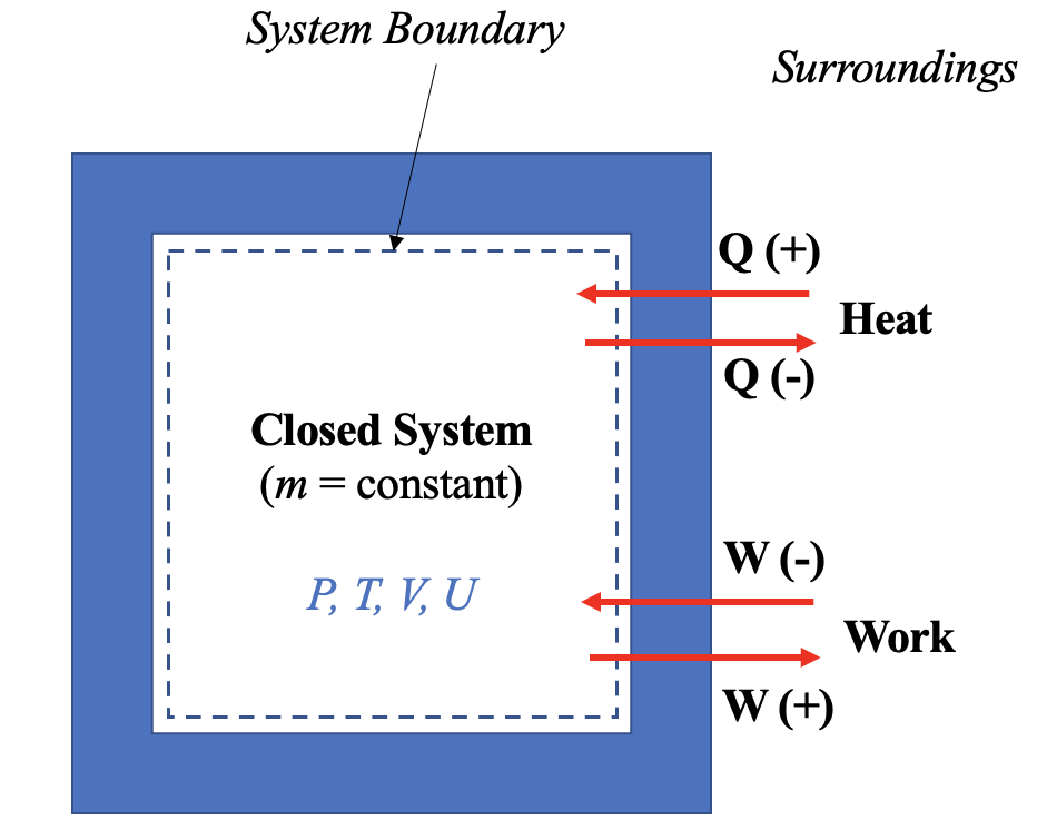
[latex]Q[/latex]: heat transfer in a process. A common sign convention: positive sign (+) for the heat transfer into a system, and negative sign (-) for the heat transfer out of a system. In short, the sign for heat transfer: in (+), out (-). See Figure 4.4.1.
[latex]W[/latex]: work done by or to a system. A common sign convention: positive sign (+) for the work output (work done by a system to its surroundings), and negative sign (-) for the work input (work done by the surroundings to the system). In short, the sign for work: in (-), out (+). See Figure 4.4.1.
Subscripts 1 and 2 refer to the initial and final states of a process.
The following procedure may be followed when solving problems with the first law of thermodynamics.
- Sketch the physical system described in the problem and show its main components.
- Set up an appropriate closed system by drawing the system boundary. How a system is set up may determine if a means of energy transfer can be regarded as heat or work.
- Indicate the heat and work transferred into or out of the system and their signs, see Figure 4.4.1.
- Identify the type of the processes (e.g., isobaric, isothermal, isochoric, polytropic, or isentropic). Show the processes on the [latex]P-v[/latex] and [latex]T-v[/latex] diagrams if possible, and list all of the known and unknown states.
- Apply the first law of thermodynamics to the closed system, eliminating the terms that are not applicable to the system.
- Solve for the unknowns by combining the first law of thermodynamics with the ideal gas law, thermodynamic tables, and other physical laws as appropriate.
The following examples demonstrate how to apply the first law of thermodynamics to closed systems.
Example 1
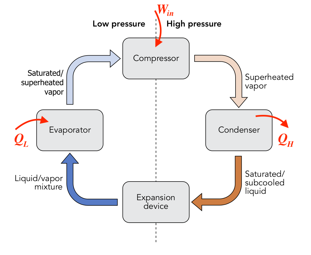
Consider the vapour compression refrigeration cycle consisting of a compressor, condenser, expansion device, and evaporator as shown. The compressor must consume work, [latex]W_{in}[/latex], from an external energy source such as electricity. The evaporator and condenser absorb and reject heat, [latex]Q_H[/latex] and [latex]Q_L[/latex], respectively. What is the relation between [latex]W_{in}[/latex], [latex]Q_H[/latex], and [latex]Q_L[/latex]?
Solution:
The vapour compression refrigeration cycle can be regarded as a closed system with the initial and final states being identical; therefore, [latex]\Delta U = 0[/latex].
[latex]\because \Delta U = 0=Q-W[/latex]
[latex]\therefore Q_L-Q_H-(-W_{in})=0[/latex]
[latex]\therefore Q_H=Q_L+W_{in}[/latex]
Note the sign convention for heat: in (+), out (-) and for work: in (-), out (+). This relation can be interpreted as the total energy transferred out of the cycle remains the same as the total energy transferred into the cycle.
Example 2
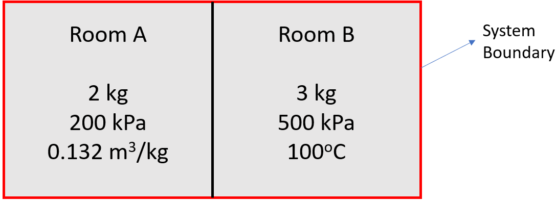
A rigid tank has two rooms, both containing R134a at the following initial states.
Room A: m= 2 kg, P=200 kPa, v=0.132 m3/kg
Room B: m= 3 kg, P=500 kPa, T=100°C
A crack is developed in the partition between the two rooms, which allows R134a in the tank to mix. Assume the mixing takes place slowly until R134a in the whole tank reaches a uniform state at 50°C. Find the heat transfer during this process. The process can be treated as a quasi-equilibrium process.
Solution:
First, set the whole rigid tank as the closed system.
Because the volume of the tank remains constant, the boundary work during the mixing process is zero; therefore, from the first law of thermodynamics,
[latex]\because \Delta U = Q - W[/latex] and [latex]W = 0[/latex]
[latex]\therefore \Delta U = Q[/latex]
The heat transfer during the process depends on the internal energies of the initial and final states.
[latex]\begin{align*} \Delta U &= U_3 - (U_1 + U_2) \\&= (m_1 + m_2)u_{3} - (m_{1}u_{1} + m_{2}u_{2}) \end{align*}[/latex]
where the subscripts 1, 2, and 3 represent the initial states of R134a in rooms A and B, and the final state of R134a in the whole tank, respectively.
Second, find the specific internal energies, u1, u2 , and u3.
Room A at the initial state: P =200 kPa, v = 0.132 m3/kg
From Table C1, at T = -10°C, Psat = 200.6 kPa, vg = 0.09959 m3/kg. Since v > vg, R134a at this state is a superheated vapour.
From Table C2, at P = 200 kPa, T = 60°C, v = 0.132057 m3/kg ≈ 0.132 m3/kg
[latex]u_1 = 427.51 \ \rm{kJ/kg}[/latex]
[latex]\mathbb{V}_A = m_{1}v_{1} = 2 \times 0.132 = 0.264 \ \rm{m^3}[/latex]
Room B at the initial state: P =500 kPa, T = 100°C
From Table C1, at T = 100°C, Psat = 3972.38 kPa. Since P < Psat, R134a at this state is a superheated vapour.
From Table C2, at P =500 kPa, T = 100 °C
[latex]u_2 = 459.65 \ \rm{kJ/kg}[/latex]
[latex]v_2 = 0.058054 \ \rm{m^3/kg}[/latex]
[latex]\mathbb{V}_B = m_{2}v_{2} = 3 \times 0.058054 = 0.1742 \ \rm{m^3}[/latex]
The final state of R134a in the whole tank: T = 50°C
[latex]v_3 = \dfrac{\mathbb{V}_{tot}}{m_{tot}} = \dfrac{\mathbb{V}_A + \mathbb{V}_B}{m_1 + m_2} =\dfrac{0.264 + 0.1742}{2+3} = 0.0876 \ \rm{m^3/kg}[/latex]
From Table C1, at T = 50°C, vg = 0.015089 m3/kg. Since v3 > vg, R134a at the final state is a superheated vapour.
From Table C2,
At P = 200 kPa, T = 50°C, v = 0.127663 m3/kg, u = 419.29 kJ/kg
At P = 300 kPa, T = 50°C, v = 0.083723 m3/kg, u = 418.19 kJ/kg
Use linear interpolation,
[latex]\because\dfrac{P_{3}-200}{300-200} =\dfrac{0.0876-0.127663}{0.083723-0.127663} =\dfrac{u_{3} - 419.29 }{418.19-419.29}[/latex]
[latex]\therefore P_3 = 291.2 \ \rm{kPa}[/latex] and [latex]u_3 = 418.287 \ \rm{kJ/kg}[/latex]
Last, substitute u1, u2 and u3 into the simplified first law,
[latex]\begin{align*} Q &= \Delta U = (m_1 + m_2)u_{3} - (m_{1}u_{1} + m_{2}u_{2}) \\& = 5 \times 418.287 - (2 \times 427.51 + 3 \times 459.65) \\&= -142.535 \ \rm{kJ}\end{align*}[/latex]
During the mixing process, the heat is transferred from the tank to the surroundings; therefore, the sign for the heat transfer is negative.
Example 3
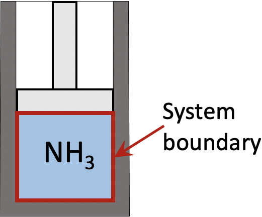
Consider 0.5 kg of ammonia in a piston-cylinder device initially at P1=100 kPa, T1=0oC. The ammonia is compressed until its pressure reaches P2=150 kPa in a polytropic process with n=1.25. Calculate the heat transfer in this process.
Solution:
First, set ammonia in the piston-cylinder as the closed system. From the first law of thermodynamics,
[latex]\because \Delta U = Q - W[/latex]
[latex]\therefore Q = W + \Delta U = W + m(u_2 - u_1)[/latex]
Second, consider the boundary work in a polytropic process. The specific volumes are unknowns
[latex]W = \dfrac{P_{2}\mathbb{V}_{2} - P_{1}\mathbb{V}_{1}}{1-n} = \dfrac{m\left({P_{2}{v}_{2} - P_{1}{v}_{1}}\right)}{1-n}[/latex]
Third, find the specific volumes and specific internal energies at both initial and final states.
At the initial state: P1 = 100 kPa, T1 = 0°C. From Table B1, Psat = 429.39 kPa at 0°C. Since P1 < Psat, ammonia is a superheated vapour.
From Table B2,
v1 = 1.31365 m3/kg, u1 = 1504.29 kJ/kg.
At the final state P2 = 150 kPa. The process is polytropic with n =1.25.
[latex]\because P_1v_{1}^n = P_2v_{2}^n[/latex]
[latex]\therefore v_2=v_1\left(\dfrac{P_1}{P_2}\right)^{1/n}=1.31365\times\left(\dfrac{100}{150}\right)^{1/1.25} = 0.94974 \ \rm{m^3/kg}[/latex]
From Table B1: at T = -25 °C and P = 151.47 kPa ≈ 150 kPa, vg = 0.771672 m3/kg. Since v2 > vg, ammonia at the final state is a superheated vapour.
From Table B2,
At P = 150 kPa, T = 20°C, v = 0.938100 m3/kg, u = 1535.05 kJ/kg
At P =150 kPa, T = 30°C, v = 0.972207 m3/kg, u = 1551.95 kJ/kg
Use linear interpolation,
[latex]\because\dfrac{T_{2}-20}{30-20} =\dfrac{0.94974-0.938100}{0.972207-0.938100} =\dfrac{u_{2} - 1535.05 }{1551.95-1535.05}[/latex]
[latex]\therefore T_2 = 23.4 \ ^ \rm{{\circ}} \rm{C}[/latex] and [latex]u_2 = 1540.82 \ \rm{kJ/kg}[/latex]
Last, the heat transfer in this process can now be found from
[latex]\begin{align*} Q &= W + \Delta U = m\dfrac{P_{2}{v}_{2} - P_{1}{v}_{1}}{1-n} + m(u_2 - u_1) \\&= 0.5 \left[ \dfrac{150 \times 0.94974 - 100 \times 1.31365}{1-1.25} + (1540.82 - 1504.29)\right] \\&= - 3.928 \ \rm{kJ}\end{align*}[/latex]
During this process heat is rejected to the surroundings; therefore, the sign for heat transfer is negative.
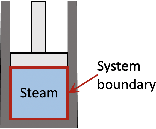
Example 4
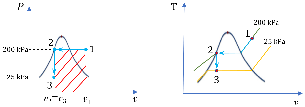
A piston-cylinder device contains steam initially at 200oC and 200 kPa. The steam is first cooled isobarically to saturated liquid, then isochorically until its pressure reaches 25 kPa.
- Sketch the whole process on the [latex]P - v[/latex] and [latex]T - v[/latex] diagrams
- Calculate the specific heat transfer in the whole process
Solution:
1. [latex]P - v[/latex] and [latex]T - v[/latex] diagrams
2. Calculate the specific heat transfer
First, set the steam in the piston-cylinder device as a closed system. From the first law of thermodynamics,
[latex]\because\Delta u = q - w[/latex]
[latex]\therefore q= \Delta u + w = (u_3 - u_1) + w[/latex]
Second, analyze the processes.
The process is isobaric from state 1 to state 2, then isochoric from state 2 to state 3. The specific work is the shaded area of the rectangle shown in the [latex]P - v[/latex] diagram; therefore,
[latex]w = P_1(v_3 - v_1)[/latex] and [latex]v_2 = v_3[/latex]
Third, determine the specific volumes and specific internal energies at states 1 and 3.
At state 1, P1 = 200 kPa and T1 = 200oC.
From Table A2,
v1 = 1.08048 m3/kg, u1 = 2654.63 kJ/kg
State 2 is saturated liquid water at P2 = 200 kPa.
From Table A1,
At T = 120 oC, P = 198.67 kPa, vf = 0.001060 m3/kg
At T = 125 oC, P = 232.24 kPa, vf = 0.001065 m3/kg
Use linear interpolation,
[latex]\because \dfrac{v_{2}-0.001060}{0.001065-0.001060} =\dfrac{T_{2}-120}{125-120} =\dfrac{200-198.67}{232.24-198.67}[/latex]
[latex]\therefore v_2 = 0.0010602 \ \rm{m^3/kg}[/latex] and [latex]T_2 = 120.2 \ ^ \rm{{\circ}} \rm{C}[/latex]
At state 3, P3 = 25 kPa. v3 = v2 = 0.0010602 m3/kg.
From Table A1, vf < v3 < vg; therefore, state 3 is a two phase mixture of saturated liquid and saturated vapour with T3 = Tsat ≈ 65oC.
vf = 0.001020 m3/kg, vg = 6.19354 m3/kg
uf = 272.09 kJ/kg, ug = 2462.42 kJ/kg
The quality and specific internal energy of the two phase mixture are
[latex]x = \dfrac{v_3 - v_f}{v_g - v_f} = \dfrac{0.0010602 - 0.001020}{6.19354 - 0.001020} = 6.5 \times 10^{-6}[/latex]
[latex]\begin{align*} u_3 &= u_f + x(u_g - u_f) \\&= 272.09 + 6.5 \times 10^{-6}(0.0010602 - 1.08048) \\&=272.10 \ \rm{kJ/kg} \end{align*}[/latex]
Note that state 3 is almost a saturated liquid with very small quality; therefore, u3 ≈ ug.
Last, calculate the specific boundary work and specific heat transfer in this whole process
[latex]\begin{align*} w &= P_1(v_3 - v_1) \\&= 200\times (0.0010602 - 1.08048) \\&= -215.884 \ \rm{kJ/kg} \end{align*}[/latex]
[latex]\begin{align*} q &=( u_3 - u_1) + w \\&= (272.10 - 2654.63) + (-215.884) \\&= -2598.4 \ \rm{kJ/kg}\end{align*}[/latex]
In this cooling process, the volume decreases, resulting in a negative specific boundary work. The temperature and the internal energy decrease too. As a result, the specific heat transfer is negative indicating a heat loss from the system to its surroundings.
Practice Problems
Media Attributions
- Vapor compression refrigeration cycle © WGisol is licensed under a CC BY-SA (Attribution ShareAlike) license
