1. Basic Concepts and Definitions
1.4 State, process, and cycle
If a system is isolated from its surroundings or is free from any unbalanced potentials, such as forced flows of mass or energy, the system will eventually reach a uniform condition called equilibrium. A system in equilibrium has uniform properties throughout the system. The following equilibrium conditions are commonly considered in thermodynamics.
-
A system that features spatially-uniform temperature is in thermal equilibrium.
-
A system free from chemical reactions is in chemical equilibrium.
-
If there is no tendency for a system to change its pressure over time, the system is in mechanical equilibrium.
-
For a system consisting of a mixture of multiple phases, such as liquid water and water vapour, if the composition of the mixture remains constant over time, the system is in phase equilibrium.
State refers to the condition of a system, which may be described by a unique set of properties, such as pressure, temperature, and specific volume. The state of a system in equilibrium is called equilibrium state. A system may change from one state to another state through a process. Let us consider a container of water initially at 10oC and 101 kPa, as an example. We set the water in the container as the system. The water is heated until its temperature reaches 50oC, while its pressure is kept constant 101 kPa. We may say that the water undergoes a constant-pressure, heating process with an initial state of 10oC and 101 kPa and a final state of 50oC and 101 kPa.
Typically, there are many possible paths that a system may take between two states; therefore, the exact path of a process is extremely important and must be clearly specified in order to describe a process! Here are the definitions of some common processes.
-
Isobaric process: the pressure remains constant in a process.
-
Isochoric process: the specific volume remains constant in a process.
-
Isothermal process: the temperature remains constant in a process.
-
Adiabatic process: no heat transfer occurs between a system and its surroundings in a process.
-
Isentropic process: the entropy remains constant in a process.
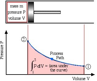
Figure 1.4.1 shows a compression process as the piston moves from the right to the left. States 1 and 2 represent the initial and final states. Each point along the process path represents an equilibrium state. If all states in a process are equilibrium states, the process is called quasi-equilibrium process. In this book, we will deal with systems in equilibrium; therefore, all states thereafter refer to equilibrium states, and all processes refer to quasi-equilibrium processes.
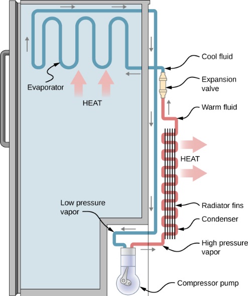
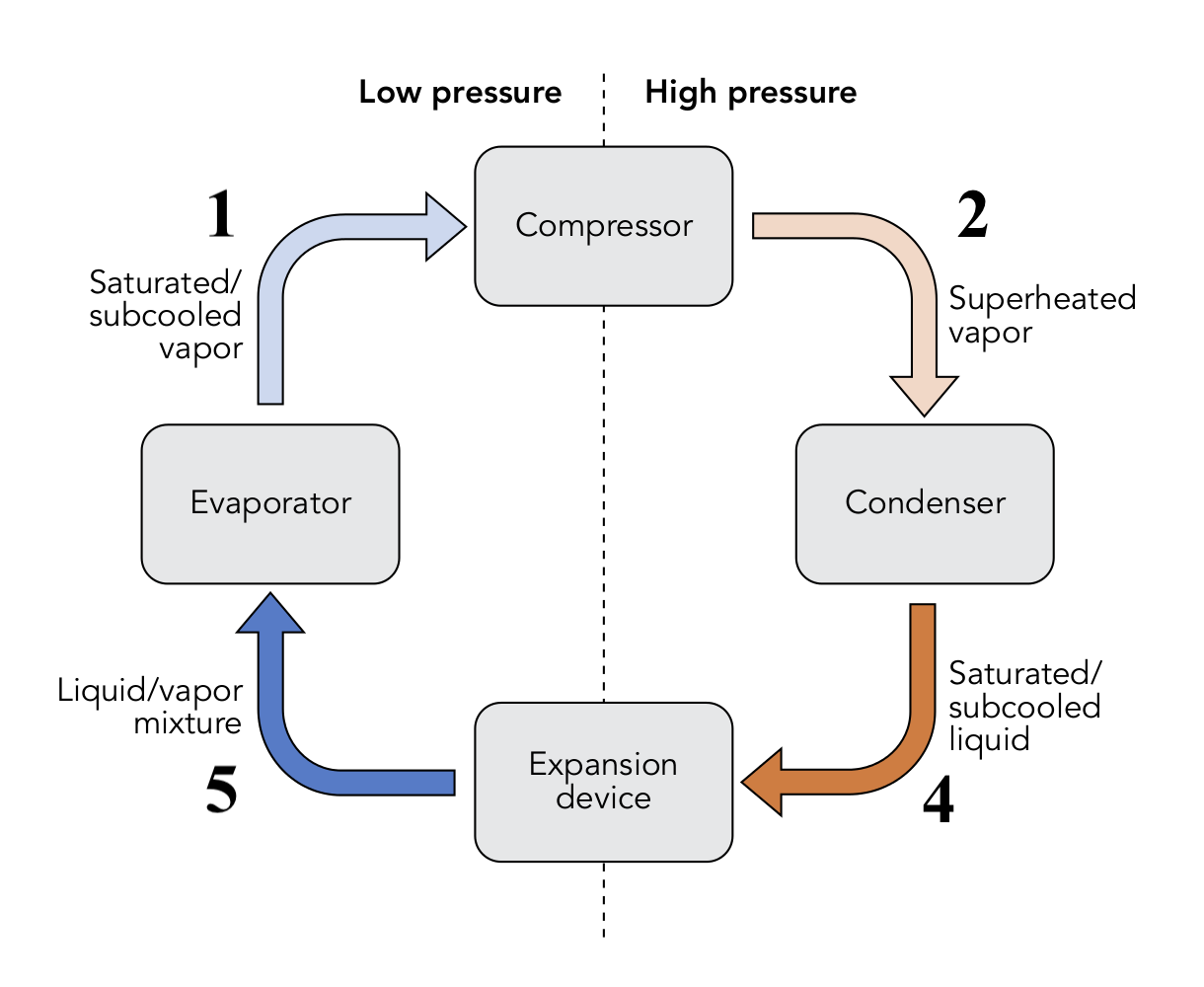
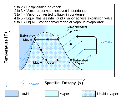
If a system undergoes a series of processes and finally returns to its initial state, we say that the system completes a cycle. Thermodynamic cycles are the basis for the operation of thermal equipment. For example, the vapour-compression refrigeration cycle is often used in conventional refrigerators and air conditioners, as shown in Figure 1.4.2. The cycle consists of four main devices: compressor, condenser, expansion valve, and evaporator. A working fluid called refrigerant circulates through these devices connected by tubes. The refrigerant in the cycle experiences phase changes between vapour and liquid, as shown in Figure 1.4.3. Phase diagrams (see details in Chapter 2) are commonly used to analyze a process or a cycle. Figure 1.4.4 illustrates the temperature-specific entropy, [latex]T-s[/latex], diagram for the vapour-compression refrigeration cycle, where the numbered dots represent different states and the lines with arrows represent different processes in this cycle. For example, the number "1" in Figure 1.4.3 and Figure 1.4.4 refers to the state of the refrigerant at the inlet of the compressor or the exit of the evaporator. The line 1-2 in Figure 1.4.4 refers to the compression process in the compressor.
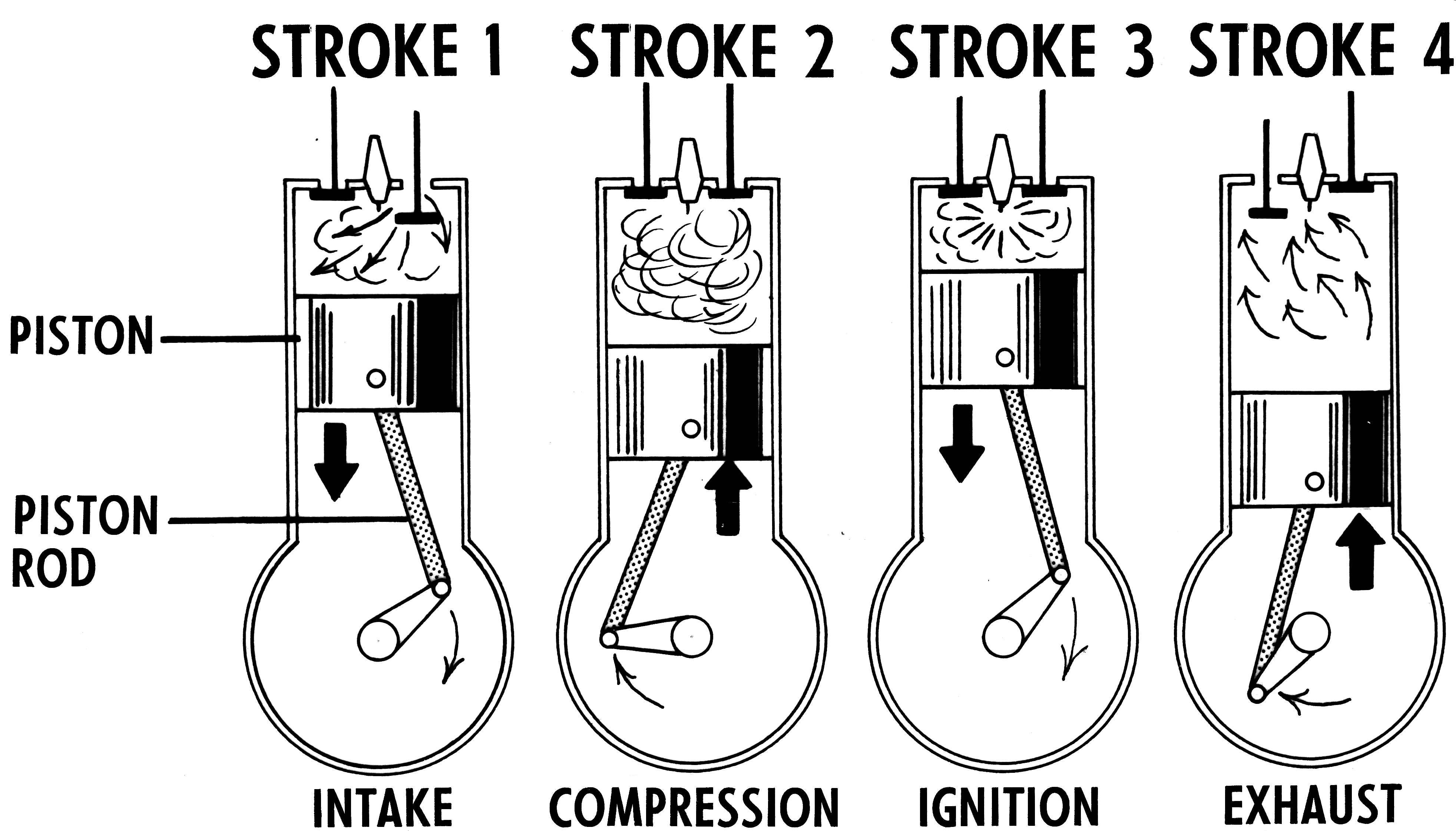
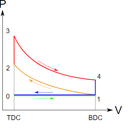
Otto cycle is another thermodynamic cycle. It is an ideal cycle that modells the operation of internal combustion engines. Figure 1.4.5 shows the cycle consisting of four strokes. The pressure-volume diagram, Figure 1.4.6, illustrates different processes in this cycle.
-
- Intake stroke, line 0-1 in Figure 1.4.6. During the intake stroke, the inlet valve opens and the outlet valve remains closed. Air is drawn into the cylinder as the piston moves to the bottom dead center (BDC).
- Compression stroke, line 1-2 in Figure 1.4.6. During the compression stroke, both valves remain closed. The air is compressed as the piston moves from BDC to the top dead center (TDC).
- Ignition and power stroke, line 2-3-4 in Figure 1.4.6. During this stroke, both valves remain closed. The piston is at TDC momentarily while the fuel-air mixture is ignited by the spark. The burning of the fuel-air mixture generates a large force, pushing the piston from TDC to BDC.
- Exhaust stroke, line 4-1-0 in Figure 1.4.6. During the exhaust stroke, the outlet valve opens and the inlet valve remains closed. The piston remains at BDC momentarily, allowing a certain amount of heat to release to the surroundings. Then the piston moves from BDC towards TDC to reject the exhaust and more heat to the surroundings.
Practice Problems
Media Attributions
- Schematic of a process © Israel Urieli adapted by DIANA BAIRAKTAROVA is licensed under a CC BY-SA (Attribution ShareAlike) license
- Refrigerator © DigitalNet99 is licensed under a CC BY-SA (Attribution ShareAlike) license
- Vapour compression cycle © WGisol is licensed under a CC BY-SA (Attribution ShareAlike) license
- T-s diagram of a vapour compression cycle © Keenan Pepper is licensed under a CC BY-SA (Attribution ShareAlike) license
- Four-stroke combustion engine © Pearson Scott Foresman is licensed under a CC BY-SA (Attribution ShareAlike) license
- Pressure-volume diagram of an Otto cycle © Luc1992 is licensed under a CC BY-SA (Attribution ShareAlike) license
Equilibrium refers to a uniform condition throughout a system.
Thermal equilibrium is an equilibrium condition. A system in thermal equilibrium has a uniform temperature everywhere.
Chemical equilibrium is a state in which the forward and backward reactions proceed at the same rate, causing no net change of the concentrations in either the reactants or the products. A system free from chemical reactions is in chemical equilibrium.
Mechanical equilibrium refers to an equilibrium condition, in which the pressure of a system has no tendency to change over time.
Phase equilibrium is an equilibrium condition. For a system consisting of a mixture of multiple phases, if the composition of the mixture remains constant over time, the system is in phase equilibrium.
A state refers to a specific condition of a system that is described by a unique set of thermodynamic properties, such as pressure, temperature, specific volume, specific enthalpy, and so on.
An equilibrium state refers to a state of a system in equilibrium.
A process refers to the change in a system from one state to another state.
An isobaric process refers to a process whose pressure remains constant.
An isochoric process refers to a process of constant specific volume.
An isothermal process refers to a process whose temperature remains constant.
An adiabatic process is a process, in which heat transfer does NOT occur between a system and its surroundings.
An isentropic process refers to a process that is reversible and adiabatic. The entropy remains constant in an isentropic process.
A quasi-equilibrium process refers to a process, in which all states are equilibrium states.
A cycle consists of a series of processes. The final state of a cycle is always identical to its initial state.

.png)