6. Entropy and the Second Law of Thermodynamics
6.2 Refrigerator and heat pump
6.2.1 Refrigerator
A refrigerator is a cyclic device, which absorbs heat from a heat sink and reject heat to a heat source by consuming work. The working fluid is called refrigerant, which usually undergoes phase changes in the cycle.
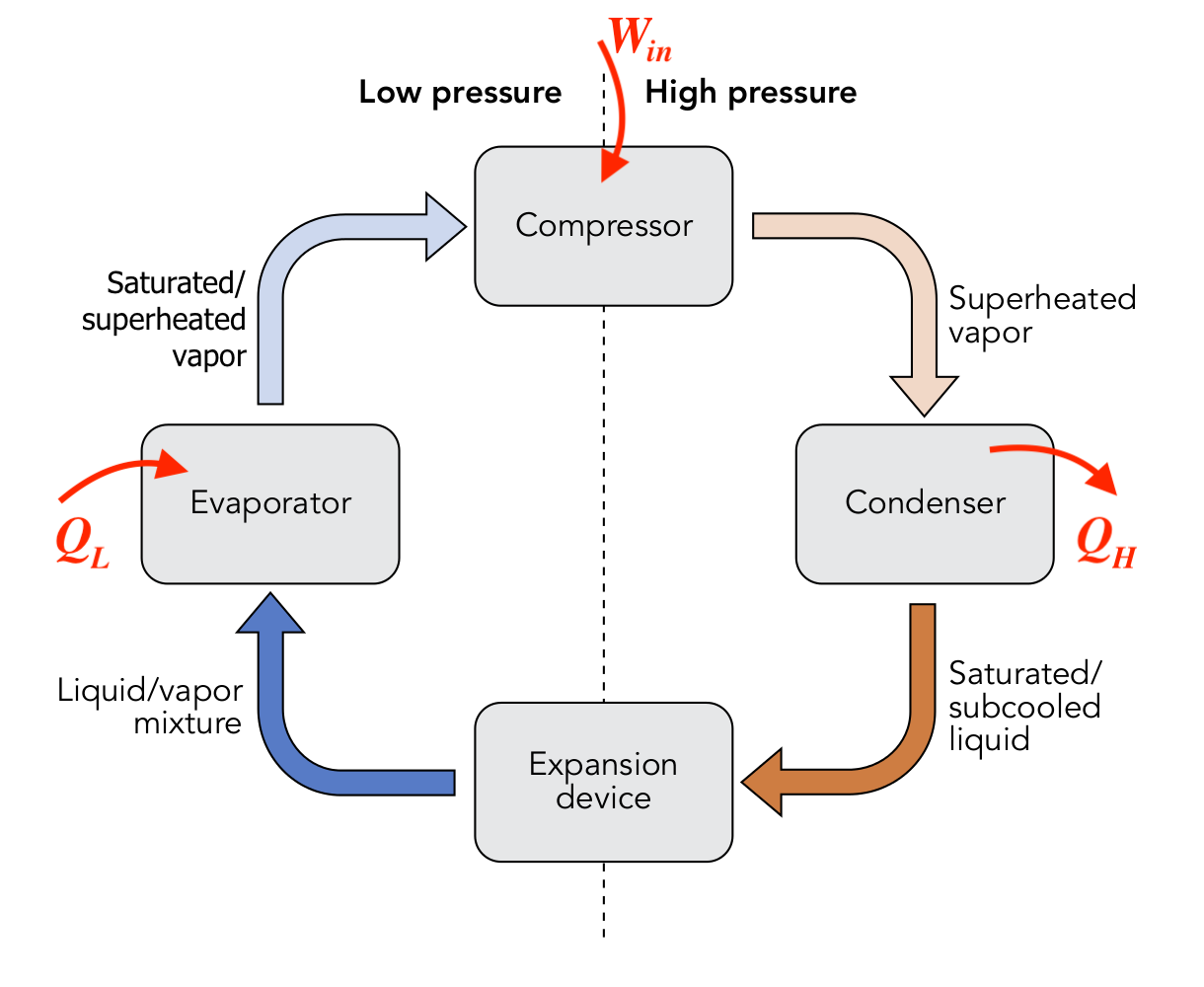
A typical vapour-compression refrigeration system consists of mainly four pieces of equipment, as shown in Figure 6.2.1:
- An evaporator, through which the low-pressure, low-temperature refrigerant absorbs heat from a heat sink (e.g., a freezer compartment or a space to be refrigerated) and changes from a two-phase mixture to a saturated or superheated vapour.
- A compressor, which is used to increase the pressure and temperature of the refrigerant vapour by consuming work.
- A condenser, through which heat is rejected to a heat source (e.g. kitchen or outdoor air). At the exit of the condenser, the refrigerant is typically a two-phase mixture or a liquid.
- An expansion valve, which is used to reduce the pressure and temperature of the refrigerant in order to achieve a liquid-vapour mixture of desirable quality at the exit of the expansion valve.
As heat cannot be transferred from a low-temperature body to a high-temperature body spontaneously in nature, refrigerators must consume work in order to operate between a heat sink and a heat source, even under ideal conditions.
Figure 6.2.2 is a schematic for analyzing the energy conservation in a refrigerator. The same schematic may be used to represent a heat pump by replacing the notation “Ref” with “HP” in the circular area.
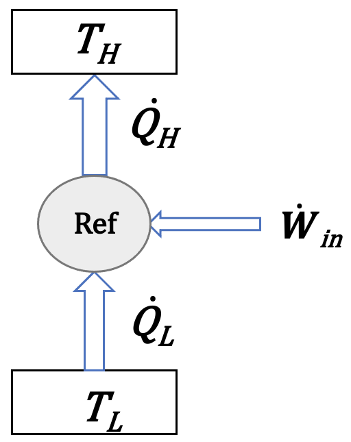
Applying the first law of thermodynamics to the cycle, we can write
[latex]{\dot{Q}}_H-{\dot{Q}}_L = {\dot{W}}_{in}[/latex]
The main purpose of refrigerators is to remove heat, [latex]\dot{Q}_L[/latex], from a heat sink (cold space); therefore, we are interested in the amount of heat that can be removed per unit of power consumption. The dimensionless ratio of [latex]\dot{Q}_L/{\dot{W}}_{in}[/latex] is called the coefficient of performance, [latex]{COP}_R[/latex], of the refrigerator. It is an indicator of the performance of a refrigerator.
[latex]{COP}_R=\displaystyle\frac{desired\ output}{required\ input}=\frac{{\dot{Q}}_L}{{\dot{W}}_{in}}=\frac{{\dot{Q}}_L}{{\dot{Q}}_H-{\dot{Q}}_L}=\frac{1}{{\dot{Q}}_H/{\dot{Q}}_L-1}[/latex]
Refrigerators are typically designed to consume a power [latex]{\dot{W}}_{in}<{\dot{Q}}_L[/latex]; therefore, [latex]COP_R > 1[/latex] in a well-designed refrigerator. A higher [latex]{COP}_R[/latex] indicates a better performance.
6.2.2 Heat pump
A heat pump uses the same vapour compression refrigeration cycle, see Figure 6.2.1, as a refrigerator. It absorbs heat from a heat sink (e.g., outdoor air in the winter) and delivers (more) heat to a heat source (e.g., indoor air) by consuming work. Applying the first law of thermodynamics to the heat pump cycle, we can derive
[latex]{\dot{W}}_{in}={\dot{Q}}_H-{\dot{Q}}_L[/latex]
Different from refrigerators, the main purpose of heat pumps is to add heat, [latex]{\dot{Q}}_H[/latex], to a heat source, such as an indoor space of a building. Therefore, we are interested in the amount of heat, [latex]{\dot{Q}}_H[/latex], that can be transferred from the condenser to the heat source per unit power consumption. The dimensionless ratio of [latex]\dot{Q}_H/{\dot{W}}_{in}[/latex] is called the coefficient of performance, [latex]{COP}_{HP}[/latex], of heat pump. It is an indicator of the performance of a heat pump. As [latex]{\dot{Q}_H} > {\dot{W}}_{in}[/latex], [latex]{COP}_{HP} > 1[/latex].
[latex]{COP}_{HP}=\displaystyle\frac{desired\ output}{required\ input}=\frac{{\dot{Q}}_H}{{\dot{W}}_{in}}=\frac{{\dot{Q}}_H}{{\dot{Q}}_H-{\dot{Q}}_L}=\frac{\dot{Q}_H/{\dot{Q}}_L}{\dot{Q}_H/{\dot{Q}}_L-1}[/latex]
Example 1
Consider a vapour-compression refrigeration cycle, Figure 6.2.1. The working fluid is ammonia.
- At the compressor inlet, P1=0.2 MPa, T1=-10oC, [latex]\dot{m}_{1} = 0.1 \ kg/s[/latex]
- At the compressor outlet, P2=1.4 MPa, T2=150oC
- At the condenser outlet, P3=1.4 MPa, T3=35oC
- At the evaporator inlet, P4=0.2 MPa
Assuming that the heat transfer and pressure drops in the connecting pipes are negligible, and [latex]\Delta PE = 0[/latex], [latex]\Delta KE = 0[/latex],
(1) determine the rate of heat absorbed by the evaporator, [latex]\dot{Q}_{L}[/latex], the power required by the compressor, [latex]\dot{W}_{in}[/latex], and the rate of heat rejected by the condenser, [latex]\dot{Q}_{H}[/latex].
(2) determine [latex]COP_R[/latex] of the refrigeration cycle
(3) If the same vapour refrigeration cycle were used as a heat pump, what would the [latex]COP_{HP}[/latex] be?
Solution:
(1) The rates of heat transfer in the evaporator and condenser and the power consumption in the compressor depend on the changes of enthalpies in these devices. First, determine the specific enthalpy of each state from Tables B1 and B2.
- State 1, compressor inlet: P1 = 0.2 MPa, T1 = -10oC. From Table B2, h1 = 1603.63 kJ/kg.
- State 2, compressor outlet: P2 = 1.4 MPa, T2 = 150oC. From Table B2, h2 = 1940.26 kJ/kg
- State 3, condenser outlet: P3 = 1.4 MPa, T2 = 35oC. From Table B1, ammonia at this state is a compressed liquid; therefore, h3 ≈ hf@35oC = 509.23 kJ/kg
- State 4, evaporator inlet: P4 = 0.2 MPa. Typically, the expansion valve is assumed well-insulated; therefore, the expansion process is adiabatic, and h4 = h3 = 509.24 kJ/kg.
The rate of the heat absorbed by the evaporator
[latex]\dot{Q}_{L} = \dot{m}(h_1 - h_4) = 0.1 \times (1603.63 - 509.23) = 109.44 \ kW[/latex]
The power consumption by the compressor
[latex]\dot{W}_{in} = \dot{m}(h_2-h_1) = 0.1 \times(1940.26 - 1603.63) =33.66 \ kW[/latex]
The rate of the heat rejected by the condenser
[latex]\dot{Q}_H = \dot{m}(h_2-h_3) = 0.1 \times(1940.26 - 509.23) = 143.10 \ kW[/latex]
From the above calculations, it is easy to verify that [latex]\dot{Q}_{H} = \dot{Q}_{L} + \dot{W}_{in}[/latex]
(2) COP of the refrigeration cycle
[latex]COP_R = \dfrac{\dot{Q}_{L}}{\dot{W}_{in}} = \dfrac{109.44}{33.66} = 3.25[/latex]
(3) If the same cycle is used as a heat pump, its COP will be
[latex]COP_{HP}= \dfrac{\dot{Q}_{H}}{\dot{W}_{in}} = \dfrac{143.10}{33.66} = 4.25[/latex]
Comment:
It is noted that both [latex]COP_R[/latex] and [latex]COP_{HP}[/latex] are greater than 1. By consuming a certain amount of power, the cycle transfers a much larger amount of heat (desirable output) either by the evaporator or by the condenser. In addition, it is always true that
[latex]COP_{HP}=COP_R+1[/latex]
because
[latex]COP_{HP} = \dfrac{\dot{Q}_{H}}{\dot{W}_{in}} = \dfrac{\dot{Q}_{L} + \dot{W}_{in}}{\dot{W}_{in}} = COP_R + 1[/latex]
Practice Problems
Media Attributions
- Vapor compression refrigeration cycle © WGisol is licensed under a CC BY-SA (Attribution ShareAlike) license
A heat engine, refrigerator or heat pump must operate between a high-temperature body and a low-temperature body. The low-temperature body is called heat sink.
A heat engine, refrigerator or heat pump must operate between a high-temperature body and a low temperature body. The high-temperature body is called heat source.
