5. The First Law of Thermodynamics for a Control Volume
5.2 Mass and energy conservation equations in a control volume
5.2.1 Steady flow and transient flow
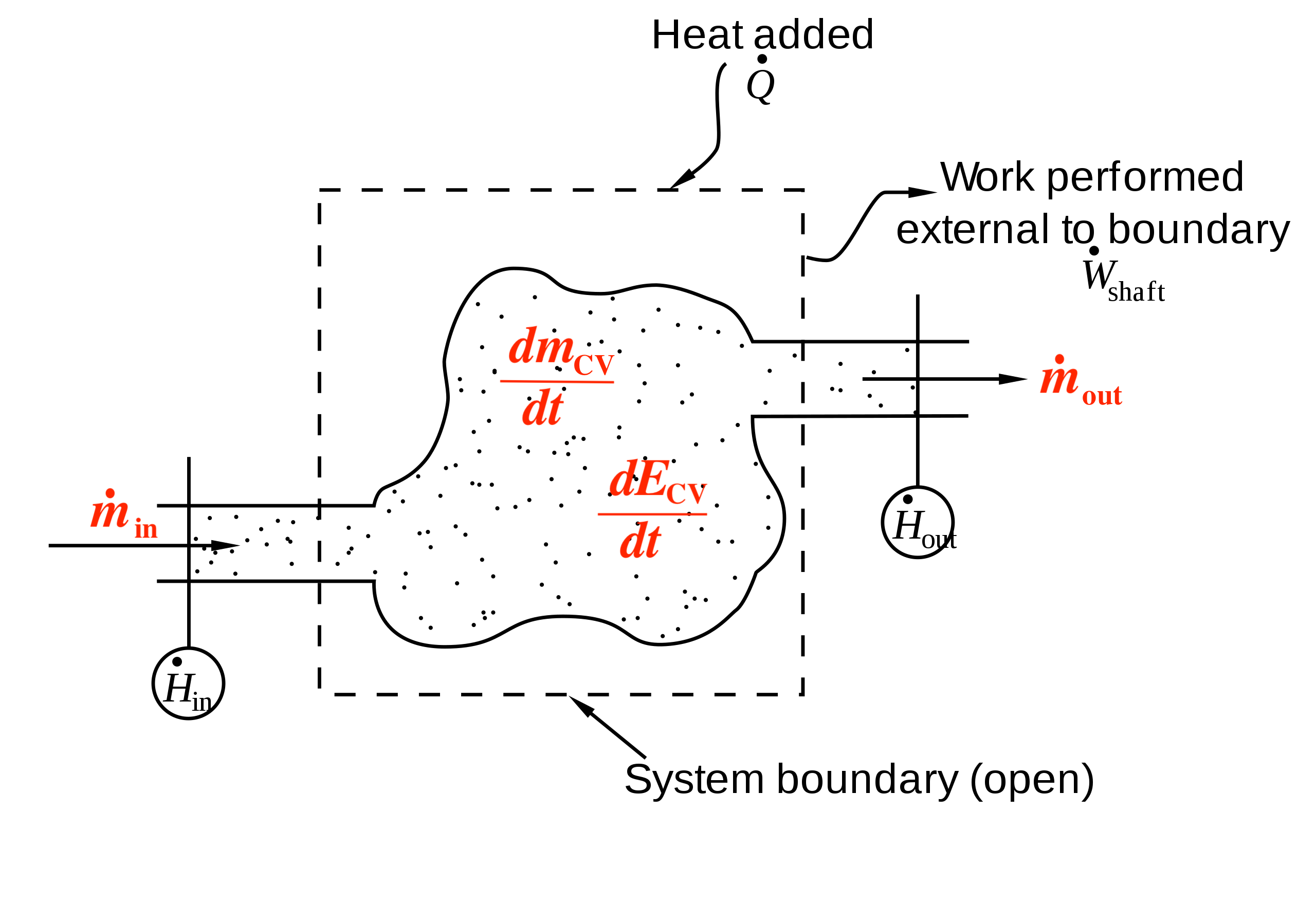
An open system allows both mass and energy to transfer across its boundary. Many thermal devices, such as compressors, turbines, and heat exchangers have inlets and outlets and can be modelled as open systems. Figure 5.2.1 is a schematic drawing of an open system with one inlet and one outlet. A control volume (C.V.), shown as the dash-lined rectangle in Figure 5.2.1, is selected for the analysis of the change of properties in the open system. A working fluid flows into and out of the control volume through the inlet and outlet. In addition, energy transfer occurs between the system and its surroundings in the form of heat and work. As a result, both mass and energy within the control volume may change over time.
If neither the mass nor the energy within the control volume change with respect to time, i.e., [latex]\displaystyle\frac{dm_{CV}}{dt}=0[/latex] and [latex]\displaystyle\frac{dE_{CV}}{dt}=0[/latex], the flow is called a steady flow. In a steady flow, the thermodynamic properties within a control volume do not change with respect to time; but they do not need to remain uniform everywhere within the control volume. The properties may vary from point to point, but at any given point, they must remain the same during the entire process. Many devices may be treated as steady flow devices after they have been in operation for a certain period of time under the same operating condition.
In a transient flow, the mass and energy within a control volume change with respect to time, i.e., [latex]\displaystyle\frac{dm_{CV}}{dt}\neq0[/latex] and [latex]\displaystyle\frac{dE_{CV}}{dt}\neq0[/latex]. Consequently, other thermodynamic properties may also change with respect to time. Flow through a device during its start-up and shut-down periods is usually treated as a transient flow.
5.2.2 Mass conservation equation
The mass flow rate and volume flow rate are defined as the mass and volume of a fluid flowing through an inlet or outlet per unit time, respectively. They are expressed as
[latex]\dot{\mathbb{V}}=\displaystyle\frac{d\mathbb{V}}{dt}=\dot{m}v=V_{avg,\ n}A[/latex]
[latex]\dot{m}=\displaystyle\frac{dm}{dt}=\rho\dot{\mathbb{V}}=\rho\ V_{avg,\ n}A[/latex]
where
[latex]A[/latex]: cross-sectional area of the inlet or outlet, in m2
[latex]m[/latex]: mass of the flow, in kg
[latex]\dot{m}[/latex]: mass flow rate, in kg/s
[latex]\mathbb{V}[/latex]: volume of the flow, in m3
[latex]\dot{\mathbb{V}}[/latex]: volume flow rate, in m3/s
[latex]V_{avg,n}[/latex]: average velocity normal to the cross-sectional area [latex]A[/latex], in m/s
[latex]\rho[/latex]: density of the working fluid, in kg/m3
[latex]v[/latex]: specific volume of the working fluid, in m3/kg
The conservation of mass, also called the continuity equation, states that mass cannot be created or destroyed. The time rate of change of mass in a control volume at a certain time equals the net mass flow rate into the control volume at that time.
[latex]\Delta \rm{mass = + in - out}[/latex]
[latex]\displaystyle\frac{dm_{CV}}{dt}=\sum{\dot{m}}_i-\sum{\dot{m}}_e[/latex]
Since [latex]\displaystyle\frac{dm_{CV}}{dt}=0[/latex] for steady flows, the mass conservation equation for steady flows is, therefore, written as
[latex]\displaystyle\sum{\dot{m}}_i = \sum{\dot{m}}_e[/latex]
where [latex]\dot{m}_i[/latex] and [latex]\dot{m}_e[/latex] represent the mass flow rates through the inlets and outlets of a control volume, respectively.
5.2.3 Energy conservation equation
The exchange of energy between a control volume and its surroundings is achieved via three mechanisms: (1) heat transfer, (2) work, and (3) mass transfer. The conservation of energy in a control volume states that the time rate of change of energy in a control volume at a certain time equals the net rate of energy transfer into the control volume at that time via the three mechanisms: heat transfer, work, and mass transfer.
[latex]\Delta \rm{energy = + in - out}[/latex]
[latex]\displaystyle\frac{dE_{CV}}{dt}={\dot{Q}}_{cv}-{\dot{W}}_{cv}+\sum{{\dot{m}}_i(h_i+\frac{1}{2}V_i^2+gz_i)}-\sum{{\dot{m}}_e(h_e+\frac{1}{2}V_e^2+gz_e)}[/latex]
Since [latex]\displaystyle\frac{dE_{CV}}{dt}=0[/latex] for steady flows, the energy conservation equation for steady flows is, therefore, written as
[latex]{\dot{Q}}_{cv}+\sum{{\dot{m}}_i\left(h_i+\displaystyle\frac{1}{2}V_i^2+gz_i\right)={\dot{W}}_{cv}+\sum{{\dot{m}}_e\left(h_e+\displaystyle\frac{1}{2}V_e^2+gz_e\right)}}[/latex]
where
[latex]h[/latex]: specific enthalpy, in J/kg
[latex]{\dot{m}}[/latex]: mass flow rate, in kg/s
[latex]{\dot{Q}}_{cv}[/latex]: rate of heat transfer, in W, across the boundary of a control volume
[latex]V[/latex]: average velocity of the working fluid through an inlet or outlet, in m/s
[latex]{\dot{W}}_{cv}[/latex]: work, in W, across the boundary of a control volume
[latex]z[/latex]: elevation of an inlet or outlet, in m
Subscripts, i and e, refer to the inlet and outlet of the control volume, respectively.
Practice Problems
Media Attributions
- Flow through a control volume © derivative work: Pbroks13 is licensed under a Public Domain license
Control volume is also called open system. It is a selected region in space, which allows mass and energy to transfer across the boundary between the system and its surroundings.
A steady flow through a control volume refers to a flow, in which the properties, such as the mass and energy of the control volume remain unchanged over time.
A transient flow refers to a flow through a control volume, in which the properties, such as the mass and energy of the control volume change over time.
