6. Entropy and the Second Law of Thermodynamics
6.10 Applications of the second law of thermodynamics in open systems
When solving problems in a control volume, the first and second laws of thermodynamics are often used together with the continuity equation and the thermodynamic tables or the ideal gas equation. The following strategy may be adapted:
- Set up a proper control volume to enclose the device of interest and identify the flow condition, i.e., steady or transient flow, through the control volume.
- Determine the relations among the mass flow rates at the inlet(s) and outlet(s) by using the continuity equation.
- Find the fluid properties at the inlet(s) and outlet(s), such as, [latex]P, T, v, h, s[/latex], by using the thermodynamic tables or equations, e.g., for an ideal gas, solid or liquid.
- Determine the rate of heat transfer, [latex]\dot Q[/latex], or other unknowns by applying the first law of thermodynamics for open systems;
- Determine the rate of entropy generation, [latex]\dot S_{gen}[/latex], or other unknowns by applying the second law of thermodynamics for open systems.
Example 1
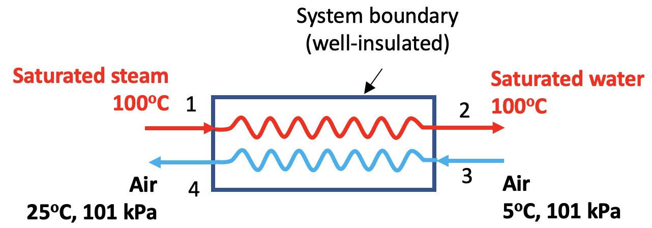
Steam is used to provide heating to air in a building through a well-insulated heat exchanger, see Figure 6.10.e1.
- Saturated steam at 100oC enters the heat exchanger at a mass flow rate of 0.5 kg/s and leaves the heat exchanger as a saturated liquid at 100oC
- Air enters the heat exchanger at 5oC, 101 kPa, and leaves at 25oC, 101 kPa.
Assume air is an ideal gas. Determine the mass flow rate of air and [latex]\dot{S}_{gen}[/latex] in this process.
Solution:
Analysis
- The mass flow rate of air can be found by using the first law of thermodynamics
[latex]\because \dot{m}_{w}(h_1 - h_2) = \dot{m}_{a}(h_4 - h_3) = \dot{m}_{a}C_p(T_4 - T_3)[/latex]
[latex]\therefore \dot{m}_{a} = \dot{m}_{w} \dfrac{h_1 - h_2}{C_p(T_4 - T_3)}[/latex]
- The rate of entropy generation can be found by using the second law of thermodynamics. Note that the heat exchanger is well-insulated.
[latex]\because \sum\dot{m}_{e}s_{e} - \sum\dot{m}_{i}s_{i} = \sum\dfrac{\dot{Q}_{k}}{T_k} + \dot{S}_{gen}[/latex] and [latex]\dot{Q}_{k} = 0[/latex]
[latex]\begin{align*}\therefore \dot{S}_{gen} &= \sum\dot{m}_{e}s_{e} - \sum\dot{m}_{i}s_{i} \\&= (\dot{m}_{w}s_{2} + \dot{m}_{a}s_{4}) - (\dot{m}_{w}s_{1} + \dot{m}_{a}s_{3}) \\&= \dot{m}_{w}(s_{2}-s_{1}) + \dot{m}_{a}(s_{4} - s_{3}) \end{align*}[/latex]
- The following properties are needed in order to complete the calculations:
- For the steam-water stream: [latex]h_1 \ , \ h_2 \ , \ s_1 \ , \ s_2[/latex]
- For the air stream: [latex]s_3 \ , \ s_4[/latex]
Now, let us solve the problem in detail.
From Table A1, we can find the specific enthalpies and specific entropies of the saturated steam and saturated liquid water at 100oC.
h1 = hg = 2675.57 kJ/kg , h2 = hf = 419.17 kJ/kg
s1 = sg = 7.3541 kJ/kgK, s2 = sf = 1.3072 kJ/kgK
From Table G1 for air: Cp = 1.005 kJ/kgK, R = 0.287 kJ/kgK
[latex]\because s_4-s_3=C_pln\displaystyle\frac{T_4}{T_3}-Rln\frac{P_4}{P_3}[/latex] and [latex]P_4=P_3[/latex]
[latex]\therefore s_4-s_3= 1.005ln\displaystyle\frac{273.15 + 25}{273.15 + 5} = 0.06978 \ \rm{kJ/kgK}[/latex]
Now, we can complete the calculations. The mass flow rate of air is
[latex]\begin{align*} \dot{m}_{a} &= \dot{m}_{w} \dfrac{ h_1 - h_2}{C_p (T_4 -T_3)} \\&= 0.5 \times \dfrac{ 2675.57 - 419.17}{1.005 (25-5)} = 56.13 \ \rm{kg/s} \end{align*}[/latex]
The rate of entropy generation is
[latex]\begin{align*} \dot{S}_{gen}&= \dot{m}_{w}(s_{2}-s_{1}) + \dot{m}_{a}(s_{4} - s_{3}) \\&= 0.5 \times (1.3072 - 7.3541) + 56.13 \times 0.06978 \\&= 0.8934 \ \rm{kW/K} \ > 0 \end{align*}[/latex]
Comment:
The heat transfer process is irreversible; therefore, the rate of entropy generation is greater than zero.
Example 2
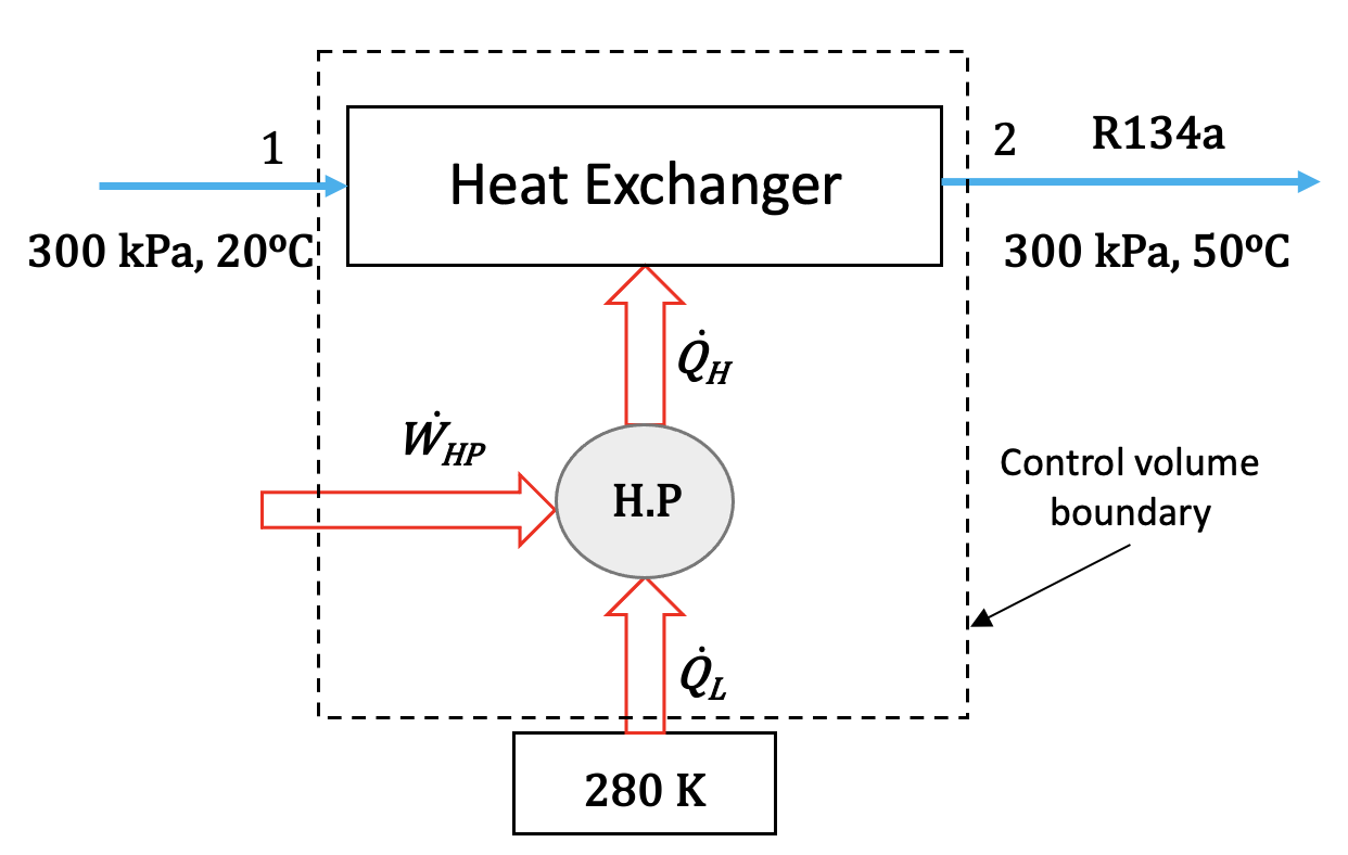
R134a at 300 kPa, 20°C is heated to 50°C isobarically in a heat exchanger. The mass flow rate of R134a is 1.5 kg/s. The heat at a rate of [latex]\dot{Q}_{H}[/latex] is supplied by a heat pump, which absorbs heat at a rate of [latex]\dot{Q}_{L}[/latex] from the ambient at 280 K, see Figure 6.10.e2. If [latex]COP_{HP}=5[/latex], and there is no heat loss in the heat exchanger, find the power input, [latex]\dot{W}_{HP}[/latex], and the rate of heat transfer, [latex]\dot{Q}_{L}[/latex]. Is this setup consisting of the heat exchanger and heat pump possible?
Solution:
The control volume is set up to enclose both the heat pump and heat exchanger, as shown in Figure 6.10.e2.
From Table C1, we can tell that, at the given pressures and temperatures, R134a remains a superheated vapour at both the inlet and the outlet of the heat exchanger. The specific enthalpies and specific entropies of R134a can be found in Table C2.
- At the inlet, P1 = 300 kPa, T1= 20oC; therefore, h1 = 416.24 kJ/kg, s1 = 1.7876 kJ/kgK
- At the outlet, P2 = 300 kPa, T2 = 50oC; therefore, h2 = 443.31 kJ/kg, s1 = 1.8755 kJ/kgK
Apply the first law of thermodynamics to the control volume.
[latex]\dot{m}h_1 + \dot{Q}_L + \dot{W}_{HP} = \dot{m}h_2[/latex]
For the heat pump
[latex]COP_{HP} = \dfrac{\dot{Q}_{H}}{\dot{W}_{HP}}[/latex] and [latex]\dot{Q}_{L} + \dot{W}_{HP} = \dot{Q}_{H}[/latex]
Combine the above three relations, we can derive
[latex]\begin{align*} \dot{W}_{HP} &= \dfrac{\dot{m}(h_2 - h_1)}{COP_{HP}} \\&= \dfrac{ 1.5 \times (443.31 - 416.24)}{5} = 8.121 \ \rm{kW}\end{align*}[/latex]
[latex]\begin{align*} \dot{Q}_{L} &= (COP_{HP} - 1)\dot{W}_{HP} \\&=(5-1) \times 8.121 = 32.484 \ \rm{kW}\end{align*}[/latex]
Apply the second law of thermodynamics to the control volume.
[latex]\because \dot{m}(s_2 - s_1) = \sum\dfrac{\dot{Q}_k}{T_k}+\dot{S}_{gen}[/latex]
[latex]\begin{align*} \therefore \dot{S}_{gen} &= \dot{m}(s_2 - s_1) - \dfrac{\dot{Q}_L}{T_{surr}} \\&=1.5 \times (1.8755 - 1.7876) - \dfrac{32.484}{280} = 0.0158 \ \rm{kW/K} \ > 0 \end{align*}[/latex]
Comment:
The rate of entropy generation in this control volume (consisting of both heat exchanger and heat pump) is positive; therefore, it is very likely that this setup can work in reality, and the processes in the heat exchanger and heat pump are irreversible.
To further verify this, we can calculate the rate of entropy generation for each individual device, i.e., heat exchanger and heat pump, separately. However, with the given information, there exists a challenge to evaluate the amount of entropy transfer due to the heat transfer provided by the heat pump to the heat exchanger. Strictly speaking, [latex]\displaystyle\int \dfrac{\dot{Q}}{T_b}[/latex] should be evaluated because the temperature of the heat exchanger varies, leading to a possible variation of temperature, [latex]T_b[/latex], at the boundary between the heat pump and the heat exchanger. The relation between the instantaneous rate of heat transfer from the heat pump to the heat exchanger, [latex]\dot{Q}[/latex], and the boundary temperature, [latex]T_b[/latex], must be obtained to enable a detailed analysis.
Here, let us perform a simplified calculation to demonstrate the concept. Assume that [latex]T_b[/latex] remains constant as the average temperature between the inlet and the outlet of the heat exchanger, thus [latex]T_b=35^ \rm{o} \rm{C}=308.15 \ \rm{K}[/latex].
Apply the second law of thermodynamics to the heat pump. Note that [latex]\dot{Q}_H=\dot{Q}_L+\dot{W}_{HP}[/latex], and [latex]\Delta s=0[/latex] for the heat pump cycle.
[latex]\begin{align*} \dot{S}_{gen, HP} &= \dot{m} \Delta s - \dfrac{\dot{Q}_L}{T_{surr}} + \dfrac{\dot{Q}_H}{T_b}\\&=0 - \dfrac{32.484}{280} + \dfrac{32.484+8.121}{308.15}= 0.015755 \ \rm{kW/K} \ > 0 \end{align*}[/latex]
Furthermore, the COP of the Carnot cycle operating between the heat sink of 280 K and the heat source of 308.15 K is
[latex] COP_{HP, rev} = \dfrac{308.15}{308.15-280}=10.9 > 5=COP_{HP}[/latex]
Because [latex]\dot{S}_{gen, HP}>0[/latex] and [latex]COP_{HP} < COP_{HP, rev}[/latex], this heat pump cycle is an irreversible, realistic cycle.
Similarly, let us apply the second law of thermodynamics to the heat exchanger.
[latex]\begin{align*} \dot{S}_{gen, HE} &= \dot{m}(s_2-s_1) - \dfrac{\dot{Q}_H}{T_b} \\&=1.5 \times (1.8755 - 1.7876) - \dfrac{32.484+8.121}{308.15} \\&= 8 \times 10^{-5} \ \rm{kW/K} \approx 0 \end{align*}[/latex]
Because [latex]\dot{S}_{gen, HE} \approx 0[/latex], the process in this heat exchanger is almost ideal and reversible. It is noted that heat losses are typically unavoidable in real devices, but they are not considered in this example. Due to heat losses from the heat exchanger, the real process will have [latex]\dot{S}_{gen, HE}>0[/latex]. Consequently, the outlet temperature may not be able to reach 50oC.
Example 3
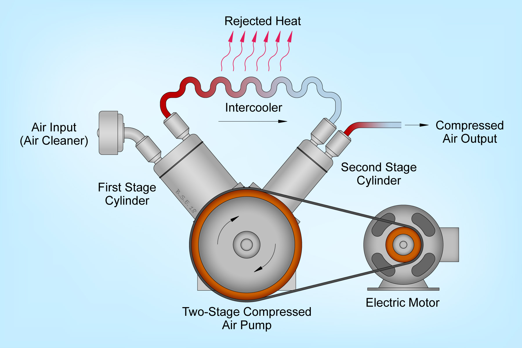
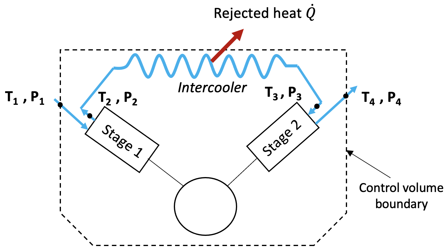
Consider an adiabatic two-stage compressor having an intercooler, as shown in Figure 6.10.e3.
- Air at 10°C, 101 kPa enters the first stage of the compressor and is compressed to 300 kPa, 150°C.
- After being cooled to 30°C in a well-insulated intercooler, the air then enters the second stage cylinder and is compressed to 900 kPa.
Assume that (1) the pressure drop in the intercooler is negligible, (2) air is an ideal gas, and (3) the two compression processes are polytropic with the same polytropic exponent. Determine
- The total specific work of the two-stage compressor.
- The specific entropy generation in each of the two stages.
- The total specific entropy generation in the system consisting of the two-stage compressor and the intercooler, assuming a constant temperature of 30°C at the system boundary.
- Assume there is no intercooler. The air from the first stage enters directly to the second stage and is compressed to 900 kPa, what is the air temperature at the exit of the second stage? What is the total specific work of the compressor? Assume the polytropic exponent remains the same in both stages.
Solution:
(1) Assume air is an ideal gas. From Table G1 for air: R = 0.287 kJ/kgK, Cp = 1.005 kJ/kgK.
The compressor is adiabatic with the following inlet and outlet conditions for each stage:
- Stage 1
- Inlet P1 = 101 kPa, T1 = 10°C
- Outlet P2 = 300 kPa, T2 =150°C
Therefore, the specific work of stage 1 is
[latex]\begin{align*} w_1 &= h_2 - h_1 = C_p(T_2 - T_1) \\&= 1.005 \times (150 - 10) = 140.7 \ \rm{kJ/kg} \end{align*}[/latex]
The polytropic exponent can be found by combining the polytropic relation and the ideal gas law.
[latex]\because P_{1}v_{1}^{n} = P_{2}v_{2}^{n}[/latex] and [latex]Pv = RT[/latex]
[latex]\therefore \dfrac{P_2}{P_1} = \left(\dfrac{T_2}{T_1} \right)^{\dfrac{n}{n-1}}[/latex]
[latex]\begin{align*} \therefore n &= \dfrac{ln\dfrac{P_2}{P_1}}{ln\left(\dfrac{P_{2}T_{1}}{P_{1}T_{2}}\right)} \\&= \dfrac{ln\dfrac{300}{101}}{ln\left[ \dfrac{300 \times (273.15 + 10)}{101 \times (273.15 + 150)}\right]}=1.58486 \end{align*}[/latex]
- Stage 2
- Inlet P3 = 300 kPa, T3 = 30°C
- Outlet P4 = 900 kPa
The air temperature at the outlet of stage 2 can be found from the polytropic relation.
[latex]\because \dfrac{P_4}{P_3} = \left(\dfrac{T_4}{T_3}\right)^{\dfrac{n}{n-1}}[/latex]
[latex]\begin{align*} \therefore T_4 &= T_3 \left(\dfrac{P_4}{P_3}\right)^{\dfrac{n-1}{n}} \\&= (273.15 + 30) \times \dfrac{900}{300}^{\dfrac{1.58486 -1}{1.58486}} \\&= 454.7 \ \rm{K} = 181.56^ \rm{o} \rm{C}\end{align*}[/latex]
Therefore, the specific work of stage 2 is
[latex]\begin{align*} w_2 &= h_4 - h_3 = C_p(T_4 - T_3) \\&= 1.005(181.56 - 30) = 152.31 \ \rm{kJ/kg} \end{align*}[/latex]
The total specific work of the two stage compressor is
[latex]w_{tot} = w_1 + w_2 = 140.7 + 152.31 = 293 \ \rm{kJ/kg}[/latex]
(2) Both stages are adiabatic; therefore, for each stage
[latex]\because \dot{m}(s_e - s_i) = \displaystyle\sum\dfrac{\dot{Q}_k}{T_k}+\dot{S}_{gen}[/latex] and [latex]\dot{Q}_{k} = 0[/latex]
[latex]\therefore s_{gen} = \dfrac{\dot{S}_{gen}}{\dot{m}} = s_e - s_i = C_{p}ln\dfrac{T_e}{T_i} - Rln\dfrac{P_e}{P_i}[/latex]
For stage 1,
[latex]\begin{align*} s_{gen, 1} &= C_{p}ln\dfrac{T_2}{T_1} - Rln\dfrac{P_2}{P_1}\\&= 1.005ln\dfrac{(273.15 + 150)}{(273.15 + 10)} - 0.287ln\dfrac{300}{101} \\&= 0.0913 \ \rm{kJ/kgK} \end{align*}[/latex]
For stage 2,
[latex]\begin{align*} s_{gen, 2} &= C_{p}ln\dfrac{T_4}{T_3} - Rln\dfrac{P_4}{P_3} \\&= 1.005ln\dfrac{454.7}{(273.15 + 30)} - 0.287ln\dfrac{900}{300} \\&= 0.0921 \ \rm{kJ/kgK} \end{align*}[/latex]
(3) To calculate the total specific entropy generation in the system consisting of the compressor and the heat exchanger, we can set up the control volume as shown in Figure 6.10.e4.
The specific heat transfer rejected from the cooler to the surroundings is
[latex]\begin{align*} q &= \dfrac{\dot{Q}}{\dot{m}} = h_2 - h_3 = C_p(T_2 - T_3) \\&=1.005 \times (150 - 30) = 120.6 \ \rm{kJ/kg} \end{align*}[/latex]
Apply the second law of thermodynamics to the control volume as outlined in Figure 6.10.e4, we can find the total specific entropy generation.
[latex]\because \dot{m}(s_e - s_i) = \displaystyle\sum\dfrac{\dot{Q}_k}{T_k}+\dot{S}_{gen}[/latex]
[latex]\therefore \dot{m}(s_4 - s_1) = \dfrac{-\dot{Q}}{T_{surr}}+\dot{S}_{gen}[/latex]
[latex]\therefore s_{gen} = \dfrac{\dot{S}_{gen}}{\dot{m}} = (s_4 - s_1) - \dfrac{-q}{T_{surr}}[/latex]
Since
[latex]\begin{align*} s_4 - s_1 &= C_{p}ln\dfrac{T_4}{T_1} - Rln\dfrac{P_4}{P_1} \\&=1.005 ln\dfrac{454.7}{(273.15 + 10)} - 0.287ln\dfrac{900}{101} \\&= -0.1517 \ \rm{kJ/kgK} \end{align*}[/latex]
Therefore, the total specific entropy generation is
[latex]\begin{align*} s_{gen}&= (s_4 - s_1) - \dfrac{-q}{T_{surr}} \\&= -0.1517 + \dfrac{120.6}{(273.15 + 30)} =0.246 \ \rm{kJ/kgK} \ > 0 \end{align*}[/latex]
Comment:
Compare the results from part (2) and part (3), [latex]s_{gen} > s_{gen,1} + s_{gen,2}[/latex], because the heat transfer process in the heat exchanger is irreversible and generates additional entropy.
(4) If the air is directly compressed from P1 = 101 kPa to P4 = 900 kPa in a polytropic process with n = 1.58486, then its final temperature at the exit of stage 2 will be
[latex]\because \dfrac{P_4}{P_1} = \left(\dfrac{T_{4'}}{T_1}\right)^{\dfrac{n}{n-1}}[/latex]
[latex]\begin{align*} \therefore T_{4'} &= T_1 \left(\dfrac{P_4}{P_1}\right)^{\dfrac{n-1}{n}} \\&= (273.15 + 10) \left(\dfrac{900}{101}\right)^{\dfrac{0.58486}{1.58486}} \\&= 634.7 \ \rm{K} = 361.5^{°} \rm{C} \end{align*}[/latex]
The specific work of the compressor will be
[latex]w_{tot'} = C_p(T_{4'} - T_1) = 1.005 \times (361.5 - 10) = 353.3 \ \rm{kJ/kg}[/latex]
Comment:
Intercoolers are commonly used in multiple-stage compressors. Without intercoolers, the air temperature in the compressor may increase significantly, which may reduce the efficiency of the compressor. In addition, by comparing the specific work in part 1 and part 4, [latex]w_{tot'}>w_{tot}[/latex], it is apparent that without intercoolers, the compressor will need to consume much more power in order to achieve the same final pressure.
Practice Problems
Media Attributions
- Two stage compressor with intercooler © Brian S. Elliott is licensed under a CC BY-SA (Attribution ShareAlike) license
