3 Tooling and Blade Selection
Almost exclusively, modern table saw blades have teeth made of tungsten carbide, a chemical compound containing equal parts tungsten and carbon. It is approximately twice as stiff and double the density as steel. Carbide can cut all wood products, dense composite materials such as Corian™, and non-ferrous metals such as brass, copper and aluminum. Carbide is extremely hard, therefore it maintains sharpness over a long period of use in the woodworking shop. The flip side of this extreme hardness is that it is brittle.
- Use care when installing the saw blade not to touch the teeth to the surrounding saw casting.
- Do not set saw blades down directly on the cast iron saw table.
- Do not place carbide cutters of any kind in contact with each other- they can dull and chip easily.
- Use a dedicated saw blade holder, or use a protective layer between the blades. A simple square of cardboard can work.
Carbide is too hard to sharpen without diamond tooling, and modern saw blades are highly accurate cutting tools. When carbide blades require sharpening, they are sent out to a sharpening service. Most companies use CNC (computer numerically controlled) technology to sharpen the blades.
Selecting the correct saw blade is critical to safe use of the table saw as well as obtaining a quality cut. Table saw blades fall broadly into five categories: crosscut, triple chip, rip, combination blades (simple & planer style), dado cutters and moulding heads. Knowing the components that make up a blade and understanding the geometry will allow you to select the correct blade for the cutting operation.
Saw Blade Components
While the geometry of circular saw blades varies, they are comprised of the same basic components.
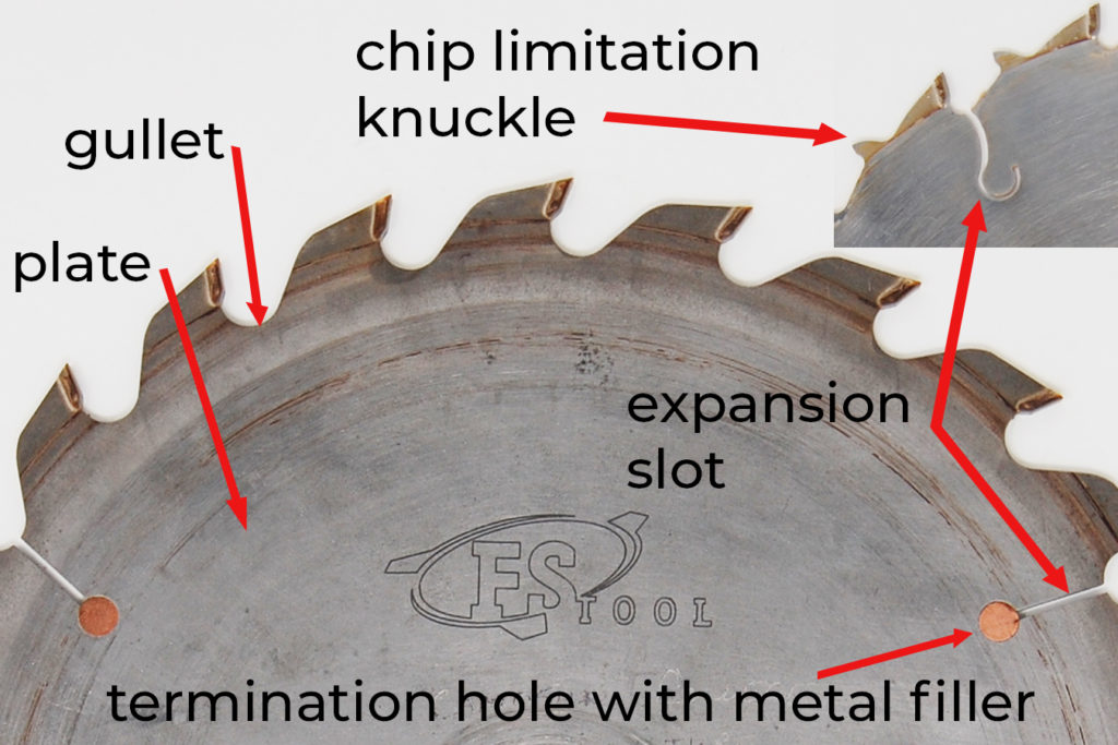
Plate
The plate comprises the main body of the blade. It may be stamped or laser cut. Laser cut blades are more expensive, the quality ones are very flat and stable and run quieter than stamped blades. In both types of blades, the plate must be flat and true to produce accurate cuts and prevent excessive noise. All plate bodies are thinner than the teeth to provide clearance to the work piece, some also have a friction reducing coating such as Teflon™. The hole in the blade that allows it to mount on the arbor shaft is called the bore. Common arbor sizes are 1/2″, 5/8″, 3/4″, 7/8″, 1″, 20 mm, 30 mm, and 32 mm. A 5/8″ arbor is common on portable, contractor and cabinet table saws sold in Canada.
Expansion slot, termination hole, metal filler
Saw blades heat up in use due to friction, heat causes the plate to expand. To prevent the plate from warping, most blades have expansion slots to allow for expansion without impacting the performance of the blade. The termination hole at the bottom of the slot reduces stress on the surrounding metal. In some blades, the termination hole is filled in with a soft metal such as copper which helps reduce noise.
Gullet
The gullet is the space between the teeth of the blade, it has a smooth rounded shape. The purpose of the gullet is to give the chips a place to go immediately after they have been generated by cutting action. Rip blades have deep gullets which help clear the longer, stringy chips that are created when cutting with the grain in solid wood. Deeper gullets clear chips more effectively.
Chip limitation knuckle
Blades designed for ripping solid wood have fewer teeth and deep gullets. This leaves a lot of space between the teeth. With this blade geometry, it is possible to feed the stock very quickly into the saw blade, which can create a kickback hazard. To help prevent this, the plate can be extended behind the tooth to prevent feeding too aggressively into the next tooth. This is known as a chip limitation knuckle.
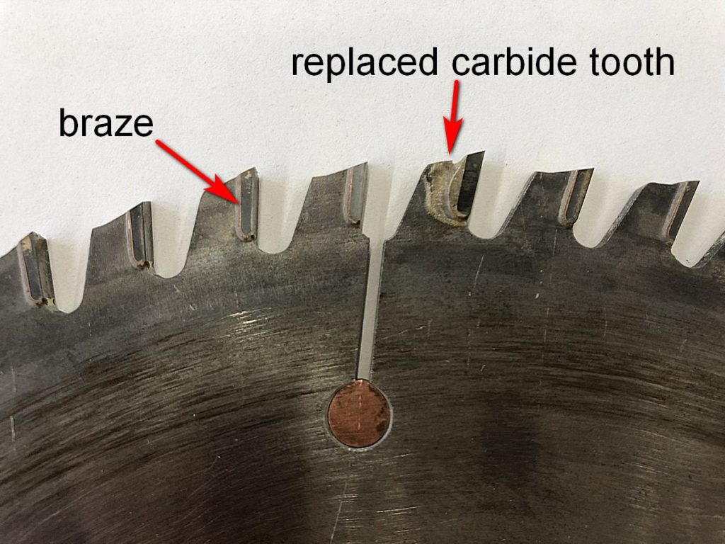
Braze
Individual carbide teeth are attached to the plate with a process called brazing. If you look closely, you will see a thin gold coloured zone between the plate and the tooth, this is the braze. Better saw blades achieve a stronger connection between the teeth and the plate by shaping the plate to accept the tooth on two edges. If a carbide tooth is damaged on a quality saw blade, it can be replaced by a company that sharpens saw blades.
Saw Blade Geometry
The differences between the saw blades have to do with blade geometry. It is important to understand the following terms. These universal terms relate to other types of cutting tools, including hand saws and router bits.
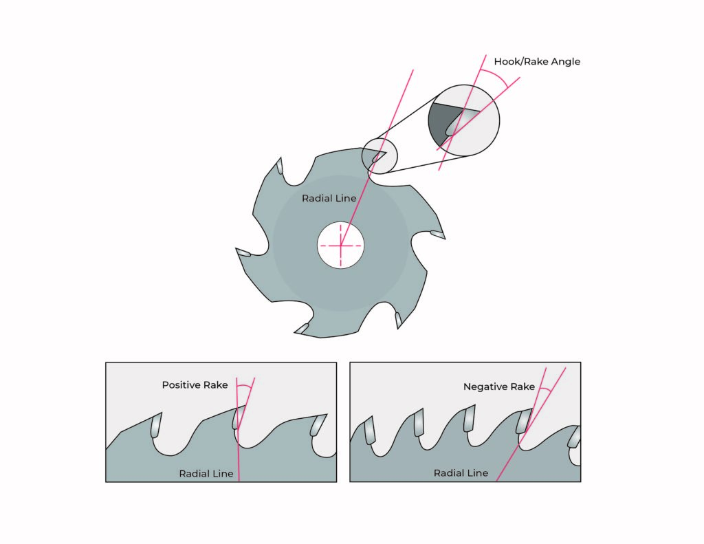
Radial line
Imagine a line drawn from the center of the saw blade to the outer edge. This is the radial line that other saw geometry relates to.
Hook angle or rake
The angle of the tooth relative to the radial line. Hook angle is a primary determinant of how aggressive a saw will cut. Rake angles range from -6° to 20°.
If the face of the tooth is in line with the radial line, it is said to have a neutral rake.
If the face of the tooth leans forward from the radial line, it has a positive rake or hook. All rip blades and most crosscut blades have a positive hook. The steeper the hook, the more aggressive the cut will be. Blades for ripping solid wood commonly have angles of 20°. Blades for crosscutting range widely depending on the application (solid wood, plywood, MDF) from about 5° to 15°.
If the face of the tooth leans back from the radial line, it has a negative hook. Negative hook saw blades are used on sliding mitre saws and radial arm saws. This geometry does not have the tendency to grab and potentially self-feed into the work. Negative hook geometry is used for cutting very hard or abrasive material. Using a negative hook blade lessens the potential impact on the carbide as the lower portion of the tooth contacts first where there is more material to absorb the force.
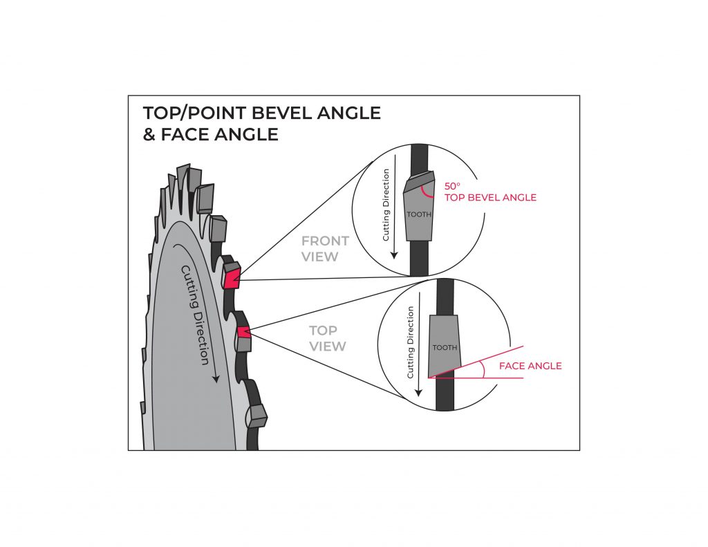
Point or top bevel angle
The angle the tooth is ground across the top. If you pick up the saw blade and look at it as if it were cutting, the bevel angle is the profile on the top of each tooth. The bevel angle is designed to sever the fibres of the material. In the case of a ripping blade, the tooth must sever at 90° to the direction of cut, therefore they have a flat-top or chisel grind. The top bevel angle would be 0°. When crosscutting, the teeth are severing fibres in line with the direction of cut, so a top bevel angle alternates from tooth to tooth. Crosscut blades have bevel angles from about 10°-20°. Specialized blades for cutting melamine have angles from 30°-40°.
Face angle
The angle of the face of the tooth as you are looking down on the blade as if it were in the table. Blades for cutting very brittle materials such as melamine or materials prone to tear-out such as veneered plywood may be ground across the face to achieve a cleaner cut.
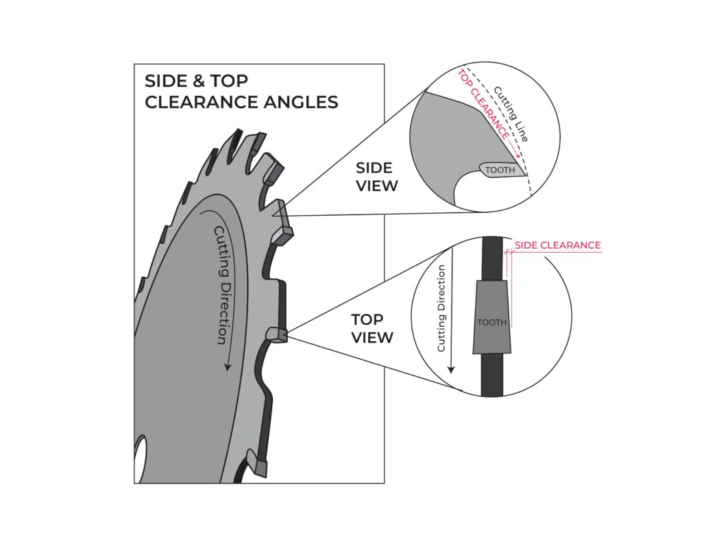
Top and side clearance
Once the tooth has made contact and cut the material, the tooth should not continue to contact the work. This allows the tooth to cut efficiently and reduces heat due to friction. Clearance angles on the side and top of the blade are necessary for efficient cutting action.
Number of teeth
Blades with more teeth cut slower, but leave a cleaner cut. Blades with fewer teeth cut faster but tend to leave a rougher surface. Blades designed for ripping solid wood have fewer teeth as more space is needed between them to clear the longer, stringy chips that are generated. Blades for crosscutting have many teeth to create a smooth, clean cut across the grain.
Common Blade Grinds and Types
Circular saw blades for woodworking can be classified according to use. There are four general blade types that are common in the woodworking shop including crosscut, triple chip, rip, and combination.
The aspects of blade geometry are combined in different configurations for optimal, safe cutting in a variety of materials. The specific tooth pattern in a circular saw blade is known as a grind. Efficient, accurate and safe cutting requires the use of the right blade. The common grinds and their applications are explained below.
Crosscut blades
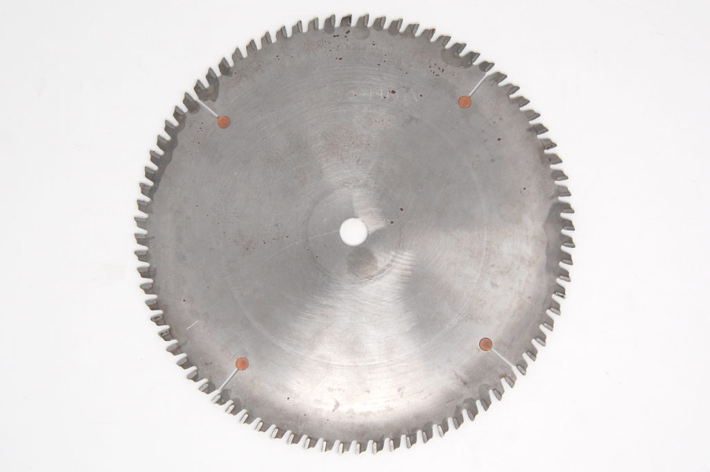
Crosscut blades are designed for crosscuts in solid wood and cutting plywood in all directions. They use an alternating top bevel (ATB) grind and have a high number of teeth per blade. A typical 10″ crosscut blade has 60-80 teeth, with 80 tooth blades producing a finer cut.
They should never be used for rip cuts as the large number of teeth and the rake angle require a high amount of force to feed the stock, increasing the potential for a kick back. They can overheat and burn the wood if used for ripping solid stock.
ATB Alternating top bevel with a positive rake
![]()
- This tooth pattern has an alternating sloped top grind that can come in varying degrees of angle. The 15 degree is typical for general purpose crosscutting of wood and plywood. The positive rake indicates that the tooth ″leans forward″ which helps the blade bite into the material without a large amount of feed pressure. Typical number of teeth on a 10″ saw blade, 60-80, up to 120.
Hi-ATB High angle alternating top bevel
![]()
- These come in a 30 to 40 degree top bevel with a negative rake. This version is especially suited to extra clean top and bottom cutting in chip and tear-out prone materials such as melamine or thin veneered plywood. This blade is also very effective in mitre or chop saw applications for clean mitre cutting of wood mouldings. Typically 80 teeth on a 10″ saw blade, up to 120.
Triple chip blades
These blades are designed for cutting hard and abrasive materials such as melamine, composite materials, and non-ferrous metals. Triple chip saw blades look similar to crosscut blades, but a closer look reveals an important difference in the tooth geometry. The teeth are not angled across the top, and the corners of alternating teeth are beveled. This helps protect the brittle carbide teeth from being damaged or prematurely worn by hard materials. While this grind will stand up well to cutting materials such as melamine, it does not produce as clean a cut on the back side as an ATB or Hi-ATB grind, and should be used with a scoring blade.
Only triple chip blades should be used for cutting non-ferrous metals such as copper, aluminum and brass.
TCG Triple chip grind

- This pattern looks like the rooftop of a barn when you look at it face on. This tooth has a ″ploughing″ action that is especially effective when cutting man-made materials like particle board, melamine (best used along with a scoring blade) and when coupled with a negative rake, plastics, solid surface and aluminum. Typically, 80 teeth on a 10″ saw blade, up to 120.
Ripping blades
Ripping requires severing the long fibres of solid wood at 90° to the kerf. To accomplish this, the teeth of these blades are shaped straight across the top to cut the fibres ahead of the tooth removing the waste. This type of flat-top tooth is also known as a raker tooth. Rip blades have fewer teeth, with large gullets to clear the long, stringy fibres that are generated. They can leave somewhat rough surface, particularly if used for crosscutting.
While ripping blades commonly have this flat top grind, some blades may also have the corners of every 3-4 teeth beveled, as in the triple chip grind. These teeth also have a slightly greater cutting depth, allowing these teeth to remove the bulk of the material while the flat top grind squares up the kerf. They tend to leave a cleaner edge that true FTG blades. They are not desirable if the blade is used for buried cuts such as grooves, or for joinery as they do not leave a flat bottom kerf.
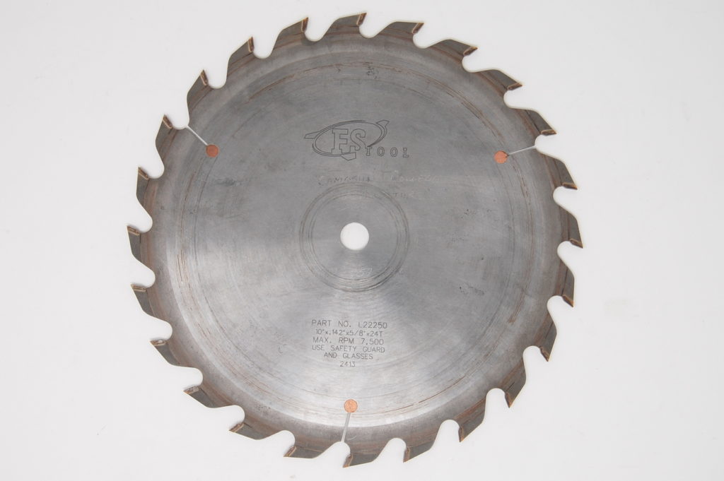
FTG Flat top grind
![]()
- The teeth on these saw blades are square top. The most common place you will see these teeth is for ripping (with the grain) solid wood. Usually has a fairly aggressive positive rake and lots of space between each tooth, these blades will saw through solid lumber quickly. With a fast cutting action, a fairly rough cut is the result. Typically have 24 teeth on a 10″ saw blade.
Combination blades
If a single saw is used for both crosscutting and ripping, it can be tedious and time consuming to change the blade for every cut. Combination blades will perform both rip and crosscut operations in solid wood and plywood. However, they are a compromise and usually do not perform as well as a dedicated crosscut or rip.
Simple combination blades have teeth of the same grind evenly spaced. They produce a decent rip or crosscut and are suitable for general purpose work.
Planer style combination blades group four ATB crosscutting teeth with one raker (ripping) tooth. A large gullet after the raker tooth provides space to remove the long fibres created when ripping. A quality planer combination blade can produce a good cut if kept sharp and clean.
If ripping dense wood or if the material is thick, it is better to change the saw blade and use a dedicated ripping blade as both the performance and safety is reduced.
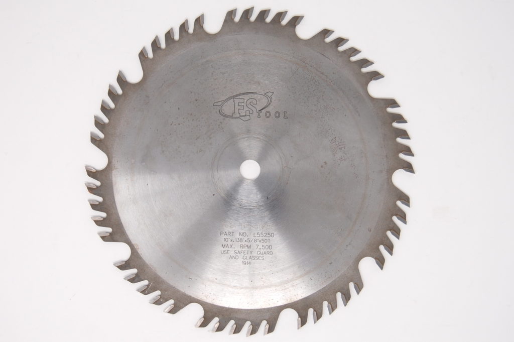
COM Combination

- The utilitarian of wood cutting blades, this blade combines the ATB and FTG patterns into one saw blade. The pattern typically consists of 4 ATB teeth followed by 1 FTG and then a large gap before the next set of teeth. Typically these have from 40-50 teeth on a 10″ saw blade.
Thin kerf blades
On most cabinet saws, the standard blade has a kerf of 1/8″ or 0.125″. Thin kerf blades have a kerf of 3/32″ or 0.094″. A thin kerf blade requires less power to execute the cut, and are a good choice for smaller table saws, particularly contractor and portable table saws. They also can be used to conserve material as the kerf is smaller.
It is important to note that most splitters are designed for standard 1/8″ saw blades. If a thin kerf blade is used the material can be impeded by the splitter, creating a hazard. Thin kerf blades, with a thinner saw plate have a tendency to vibrate, reducing the quality of the cut. They may also overheat more easily. On a left-tilting table saw, changing between a standard and thin kerf blade will necessitate changing the calibration of the rip fence.
Dado Cutters
A dado set is comprised of separate cutters that are used in combination to achieve cuts of varying widths. The set is comprised of two saw blades that are placed on the outside of the cut, and internal cutters called chippers that clear the waste between the blades.
They are commonly used to cut dadoes, grooves and rabbets, as well as other joinery such as finger joints and open mortises.
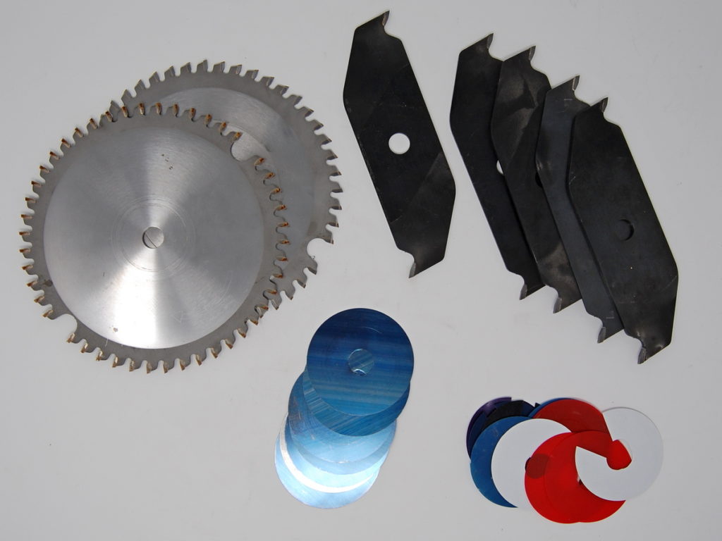
Components
The two outer saw blades in a dado set are handed, and must be used on the correct side of the cut. Each of these blades has a top bevel in one direction only to aid in severing fibres when used across the grain. Additionally, they are made with a slight relief on the inside of the plate that contacts the chippers to ensure the teeth on the different cutters do not contact one another. They may include a flat top raker tooth as well to aid in chip clearance during rip cuts in solid wood. The chippers have only two teeth with a flat-top raker grind. These should never be used on their own.
Dado blades can cut with or across the grain in solid stock and plywood and composites. Typically, a 10″ table saw will be used with an 8″ dado set. They can have from 24 to 46 teeth (per blade), with a 46 tooth set being used for fine crosscutting in hardwoods and clean cutting in materials such as melamine. 24 tooth sets are more common, and are used for general purpose work.
Installation on the saw
When installing the dado set on the saw, the chippers should be staggered radially to maintain balance of the dado stack. Care should be taken to position the teeth so they are not touching each other. This prevents damage to the brittle carbide, prevents loosening during use, and ensures the dado will cut the width it was designed to.
Set-up to obtain the desired width of cut
The cutters in a dado set are manufactured to cut in precise increments. The sizing of most commonly available dado sets is in imperial measurement. The smallest dado that can be made with the set is 1/4″ using the two outside sawblades only. Sets usually have from four to six chippers, depending on the manufacturer. The chippers are individually sized to cut 1/16″, 1/8″, and 1/4″ increments. Combining these allows cuts from 1/4″ to 13/16″ in 1/16″ increments with most sets.
Using shims
In order to achieve precise widths that differ from these 1/16″ increments, a set of shims may be used. These shims are made from thin plastic or metal, and are spaced between the cutters. When using more than a few thin shims or thicker shims, it is best practice to spread them between multiple cutters. This ensures there are no areas left uncut by spacing the chippers farther apart.
The thickness of the shims is usually indicated in decimal inches. By converting the thickness of the saw blades and chippers to decimal inches, precise widths of cut can be obtained. For example, each outer blade will cut 1/8″, or 0.125″. A dado set with the 1/16″ chipper installed will cut 0.125″ + 0.125″ (two outside blades) + 0.0625″ (chipper) for a total of 0.3125″, or 5/16″. If a dado of 0.3525 was required, dado shims equaling 0.04″ would need to be added. Measuring using Vernier or digital calipers when setting up dado blades can save time and guesswork. The part that will be fit into the dado or groove is measured with the calipers in decimal inches, then the dado stack can be configured to the correct measurement using shims. Always make a test cut to confirm.
