2 Parts of the Table Saw
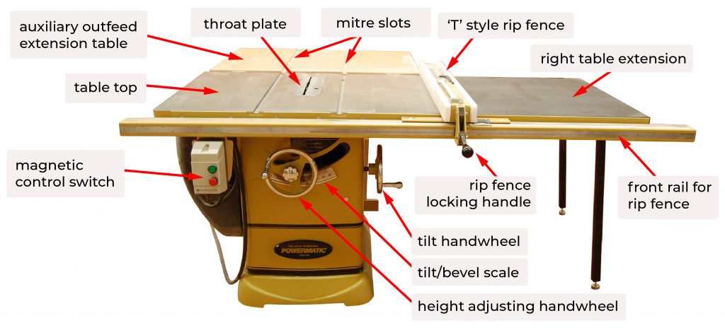
Table top
The table on a quality saw is made of cast iron, and is made up of three parts: a main table that is bolted to the saw base, and left and right extension wings that bolt to the main table. Cast iron is desirable as it has a strong dampening effect that mitigates vibration. A properly manufactured cast iron table will also remain flat and stable. Some contractor saws have a cast iron main table and stamped steel extensions on the left and right sides as they are less inexpensive. The cast iron table must be flat as it forms the reference surface for all cuts made on the saw. The extension wings should be carefully leveled with the main table at the time of assembly, and checked periodically. They provide additional working surface area.
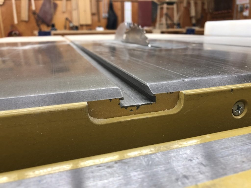
Mitre slot
Mitre slots are machined into the main cast iron table, and are perfectly parallel to the saw blade. They are used to guide jigs such as the mitre gauge. Other manufactured or shop made jigs and fixtures are used in conjunction with the mitre slots to guide work (such as a tenon jig) or increase accuracy and safety (featherboards). There are two styles of mitre slots, plain and ‘T’ slots. The T style allows the use of hardware that will clamp in place, making it versatile for mounting fixtures or stops. Mitre slots usually measure ¾ inches wide by 3/8 to ½ inches deep.
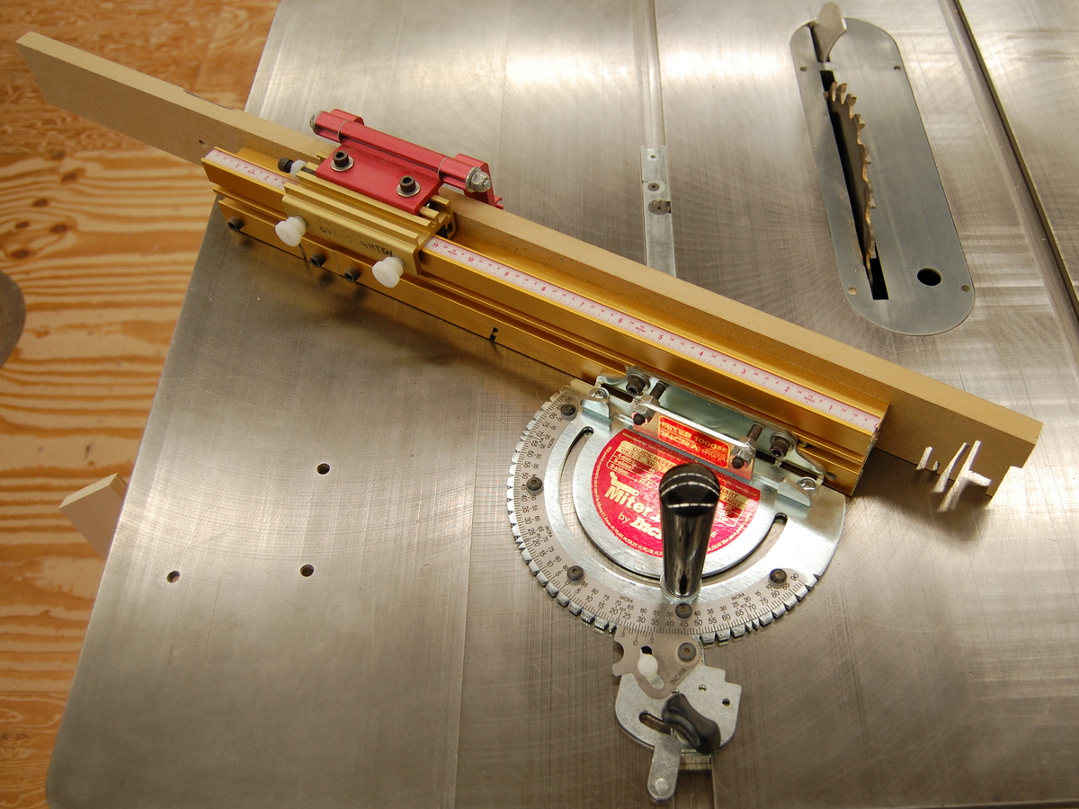
Mitre gauge
The mitre gauge is used primarily for safe crosscutting, supporting the work at 90° to the blade. Or, the gauge may be set to cut angles from 0° to 45° or greater, depending on the gauge. The gauge will run in either mitre slot, and can be set in either direction relative to the 90° position. An auxiliary fence of plywood or MDF is recommended for both safety and quality of cut. Sandpaper glued to the auxiliary fence can keep the workpiece from sliding during the cut. Mitre gauges are included as a standard accessory with all table saws. Some companies manufacture aftermarket miter gauges that are highly accurate and versatile, especially when used for mitres or complex angle work.
Throat plate or insert
The throat plate covers the opening in the saw table where the blade projects. It must be used for all cutting operations. The throat plate that comes as standard equipment from the manufacturer is usually made of aluminum, but may also be made of plastic or composite such as phenolic resin. Aluminum is used as it will not damage the carbide teeth of the saw blade if it contacts the blade.
Shop made throat plates are commonly used to provide zero-clearance cutting to the saw blade, or to allow the use of a dado cutter of any width. Having zero-clearance helps prevent small offcuts from getting lodged in the space between the blade and throat plate. They also increase the quality of the cut by preventing tear-out on the bottom of the cut where the blade exits the work.
The throat plate sits on four projections on the saw casting. It must be level with the surrounding table, and is adjustable by means of four Allen screws on the underside of the throat plate. It is very important that the back of the throat plate is not lower than the saw table, as the workpiece will catch the table and be directed into the back side of the blade, posing a kickback hazard. The manufactures’ throat plate has an access hole or finger hole for easy removal, and comes with the blade slot and splitter slot already machined into it. It is never zero-clearance as it is designed to fit the largest blade that the saw can accept (with the exception of dado cutters) with clearance on all sides.
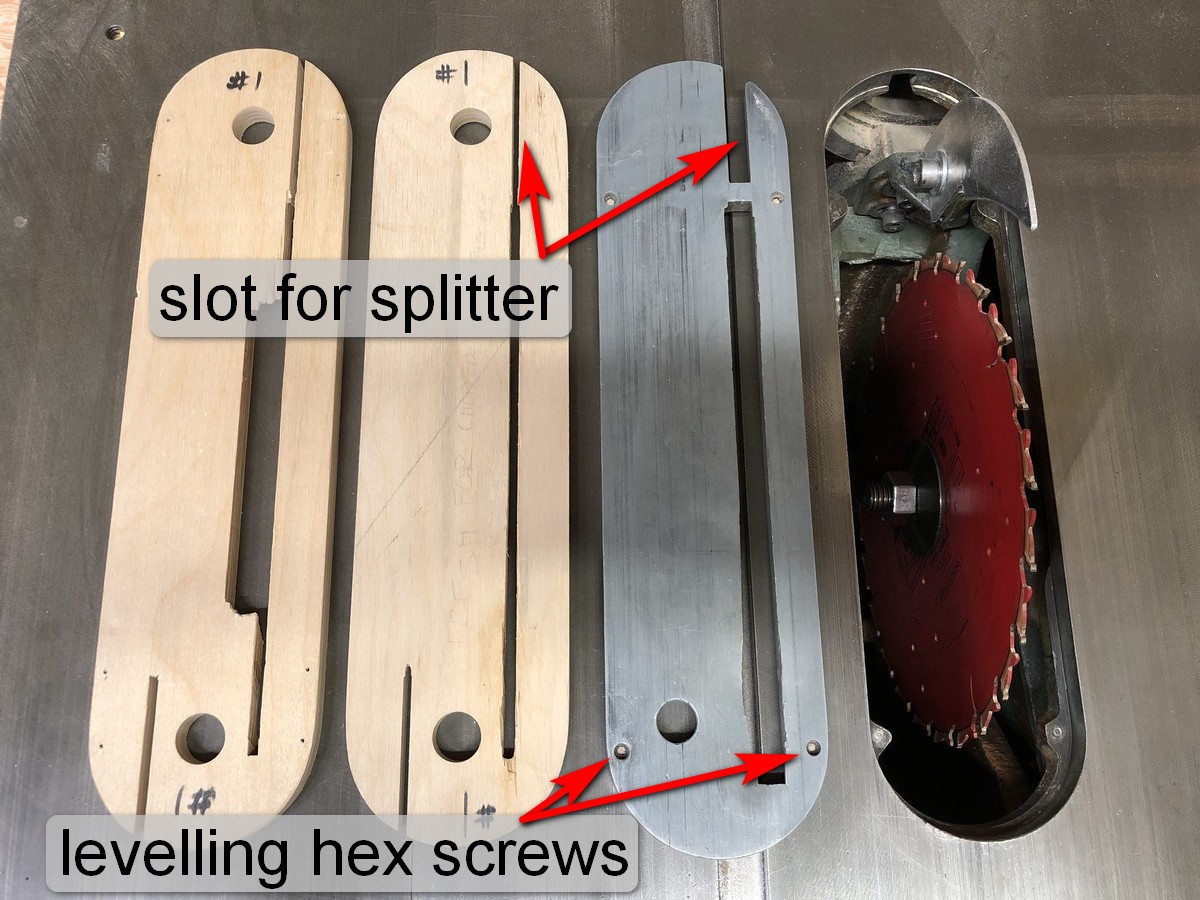
Shop made throat plate
With a shop made throat plate, the insert is usually machined out of MDF or quality plywood such as Baltic birch. Composites such as plywood or MDF are preferable to solid wood because they are stable and are not likely to have tension or flaws as is common in solid wood. They are leveled by installing set screws or small wood screws where the plate will contact the casting. The shop made throat plate has the slot for the blade cut into it while positioned on the saw. To do this safely, the rip fence may be locked in place over the right side of the throat plate, and a push stick used to hold the left side while the blade is slowly raised through the insert. Once the blade slot is cut, the access for the splitter or riving knife may be located in line with the blade. Shop made throat plates are often made to allow the use of dado cutters as the opening in factory throat plates is too small to accept them.
Splitter and anti-kickback fingers
A splitter is a thin piece of material (usually steel) that is mounted just behind the saw blade. The purpose of the splitter is to prevent material from contacting the back of the saw blade, a primary reason for a kickback. The splitter, also called a riving knife, is an important safety device that should be used whenever possible. Some operations on the table saw necessitate the removal of the splitter, such as buried cuts and the use of dado blades. Always replace it after performing these cuts.
The splitter should be aligned directly behind, and in line with the blade. It should be slightly thinner than the saw blade to allow the stock to move past it without drag. Beware of using splitters with thin kerf saw blades, most are not designed for them and your stock can bind, creating a hazard.
Some splitters come with anti-kickback fingers. These serrated steel plates pivot and move over the top surface as the material is run through the blade. If the stock is moved back out of the saw, it jams in the serrations and is prevented from kicking back. The height of the anti-kickback fingers must be set properly for them to be effective.

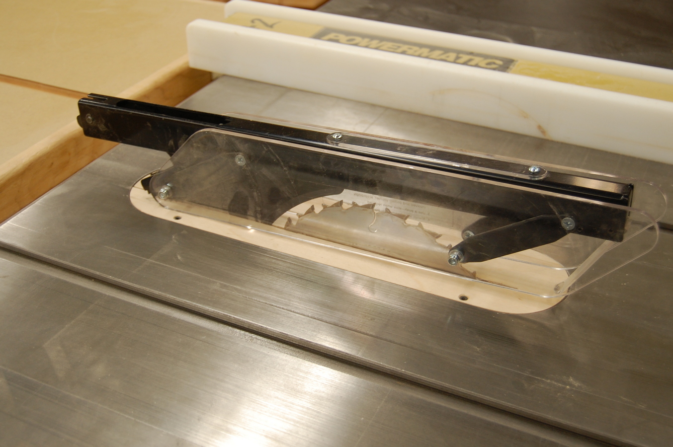
Blade guards
The blade guard is designed to protect the operator from accidental contact with the blade. They also direct sawdust and small particulate away from the operators face. There are two types of blade guards. The first type attaches to the saw trunnion (the movable part of the saw below the main table). This blade guard assembly is made up of the guard, splitter or riving knife, and sometimes anti-kickback fingers. This type of guard is typically supplied with the machine.
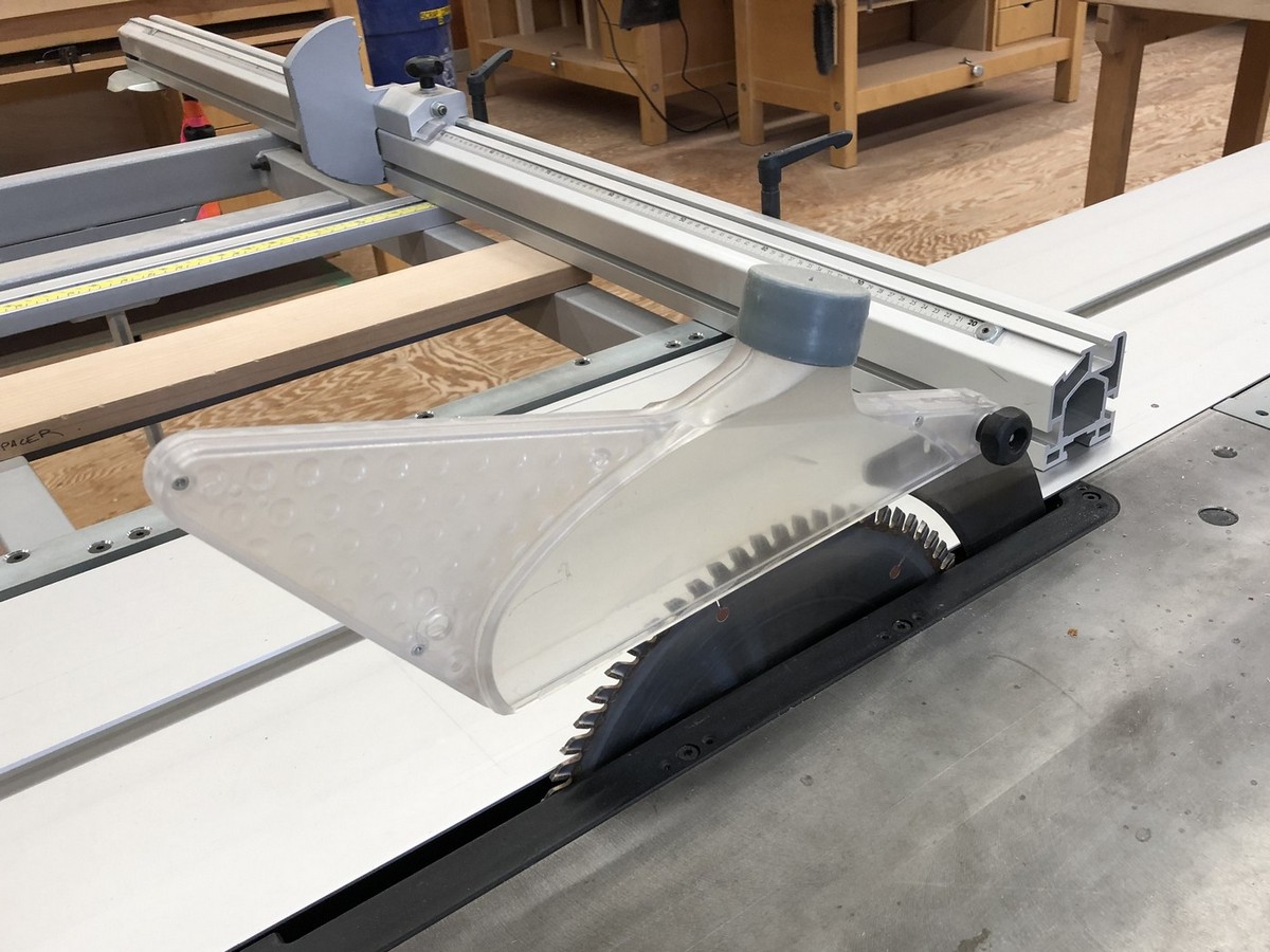
The second type of guard is an over-arm guard that usually attaches to the extension table. These guards can be purchased as an aftermarket item if the original guard is missing. They are often easy to adjust for different heights of cut, and may have dust collection. They do not have splitters or anti-kickback fingers, these should be installed in addition to the over-arm guard.
WorkSafe BC stipulates that guards may be removed for a specific operation that prevents their use, or if the guard creates a hazard as long as appropriate measures such as push sticks and feather boards are in place. The guard must be replaced after the operation is complete. Refer to worksafe reg. 12.59).
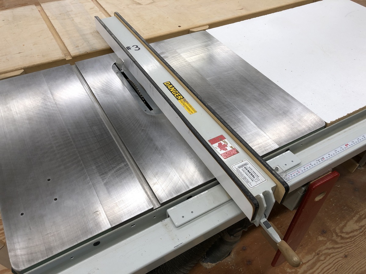
Rip fence
Rip fences are straight guiding fixtures which are secured at a measured distance from the saw blade. This kind of fence works by remaining parallel to the saw blade no matter what distance it is adjusted to, ensuring that two or more boards passed between the blade and the set fence will measure the same size.
Most new fence designs come with some type of locking mechanism that ensures that once the fence and blade are adjusted into parallel, the setting will remain consistent. The Biesemeyer ″T-Square″ and SawStop T Glide are common fences found on cabinet table saws. Most new table saws come with fences that will remain parallel to the blade. It is worth noting that while the fence can be set exactly parallel to the blade, having one or two thousandths of an inch difference between the leading and back edge of the blade can be desirable. This eliminates the teeth that are exiting the table from contacting the wood that has already been cut, resulting in a cleaner edge and possibly reducing the potential for kickback.
See also Set-up and Maintenance: Adjusting the rip fence (T-style) to the blade.
European Rip Fences
An alternative style of fence is found on saws that originate in Europe. Most sliding panel saws also use this design, which provides for the fence to be locked in different locations along its length. This allows the fence to be positioned before the blade and safely used as a moveable stop as the offcut is clear of the fence as it cut.
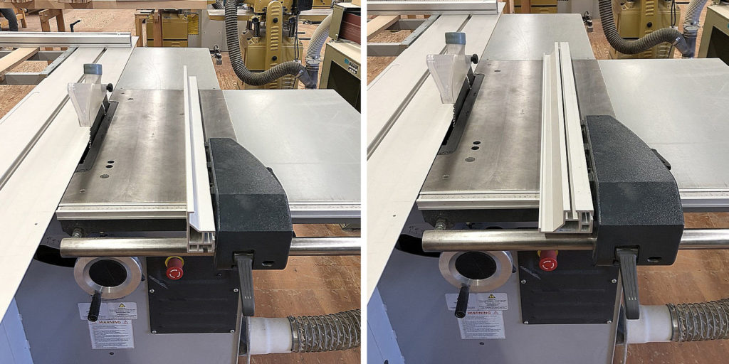
The rip fence has a high and low position which is achieved by the use of an aluminum extrusion that has two positions. The high position is used for tall or wide work, the low position allows for narrow work while leaving clearance for the saw guard to clear the fence.
Rip fence locking handle
An eccentric cam is part of the rip fence locking device, and provides ample mechanical locking force with little pressure.
Front rail for rip fence
The front rail on a ‘T’ style rip fence provides a bearing surface for the locking mechanism of the fence.
Rear rail for rip fence
The rear rail on a ‘T’ style rip fence is not needed for the operation of the fence, but provides structure for the right table extension.
Right table extension
This table provides support for larger work pieces such as sheet goods. It is a convenient place to stack parts for processing though the saw. It should be kept clean and clear of clutter. It also supports the rip fence rails on cabinet saws.
Auxiliary outfeed extension table
Almost every cabinet saw has this shop made accessory table. It prevents the work from falling off the back of the saw as it is cut. It should have slots machined in it to allow for accessories that use the mitre slots in the table top.
Magnetic control switch
Magnetic controllers are standard on all industrial saws. Magnetic switches are safer because they physically break contact when the power supply is interrupted, and won’t turn back on when the power resumes.
Power disconnect
When changing the blade, doing set-up that brings your body close to the blade, or performing maintenance, you must disconnect the machine from the power source. This can be done by unplugging the saw, or in the case of a hard-wired machine, by using the appropriate lock out procedure at the breaker panel.
Height adjusting handwheel
Turning the hand wheel raises and lowers the saw blade to adjust the depth of cut, it is always located on the front of the saw. Most hand wheels have a lock. It is not necessary to lock the hand wheel for simple through cuts, it is advisable to lock it for any operation that requires the blade height to be precise. To maintain an accurate depth of cut, start with the blade low and increase up to the desired setting. This will ensure vibration from the machine does not alter the height due to backlash in the screw mechanism.
Tilt handwheel
The tilt handwheel engages the trunnion assembly which tilts the blade relative to the table. The handwheel is located on the left or right side of the cabinet directly underneath the table. A bevel scale is located on the front of the machine and indicates the degree of tilt. There are positive 90° and 45° stops for these two common positions that can be calibrated for accuracy, refer to the owner’s manual for instructions on how to adjust them.
Table saws that tilt the blade toward the rip fence are called right tilt saws; the handwheel is located on the left side. Saws that tilt the blade away from the rip fence are called left tilt saws; the handwheel is located on the right hand side.
Left versus Right Tilt Saws
Most new cabinet saw models are left tilt. It is believed left tilt saws are safer when ripping as the workpiece is not trapped under the blade and between the fence. This has a greater risk of kickback if the workpiece rises up relative to the blade. However, bevel rip cuts can safely be performed on a right tilt saw by moving the rip fence to the left side of the blade.
It is important to note with left-tilt table saws that when the saw blade is installed, it references the left side of the saw blade against the arbor flange. Because the rip fence is on the right side of the blade, changing between thin kerf (3/32 inches) and standard saw blades (1/8 inches) will throw off the calibration of the rip fence depending on what thickness of blade was installed in the saw when the fence was calibrated. This is a major disadvantage of left tilt saws, and something to be aware of when using the rip fence scale.
Tilt/bevel scale
The scale for the blade tilt is located on the front of the saw. It is not highly accurate for setting of angles between 90° and 45°. Use a reliable layout tool such as a drafting set square, sliding ‘T’ bevel, or digital inclinometer. The trunnion assembly references positive stops at 90° and 45°, these may be need to be cleaned of debris and calibrated periodically.
Arbor assembly
The arbor assembly is comprised of the shaft, bearings, flange, arbor washer and nut. This assembly is connected to the drive system, and is where the saw blade mounts. The end of the shaft is threaded for the arbor nut that secures the blade in place. The most common arbor diameter for a 10 inch cabinet saw is 5/8 inches. Industrial panel saws have a larger arbor, commonly 30mm.
The arbor shaft usually has a left-hand thread, which is opposite to the blade’s rotation. This ensures that the nut does not loosen with use.
Trunnion assembly
The trunnion assembly is what allows the saw to tilt. The trunnions are the part that ride in semicircular trunnion brackets, these are usually visible from the throat opening looking toward the back of the saw. The entire trunnion assembly may be bolted to the saw cabinet or the underside of the cast iron table. If the saw blade is out of alignment with the miter slots, the trunnion assembly must be loosened from the mounts and adjusted.
Drive belt
Most industrial table saws use a pulley and drive belt to transfer power to the arbor. This allows the arbor assembly to be as close as possible to the underside of the table without the motor interfering, which has the advantage of allowing a greater depth of cut. The belts wear and need to be replaced periodically. Some table saws, especially smaller portable models may use a direct drive system where the motor is connected directly to the arbor.
Parts specific to the panel table saw
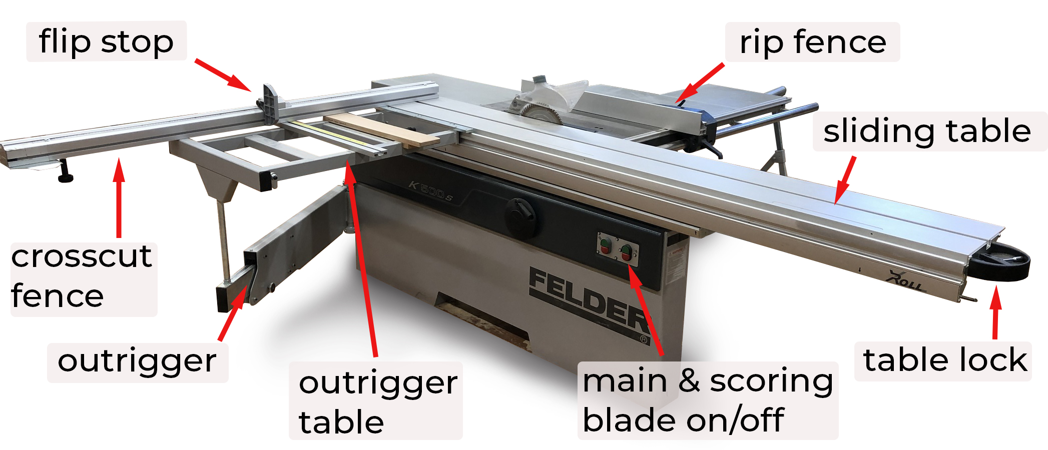
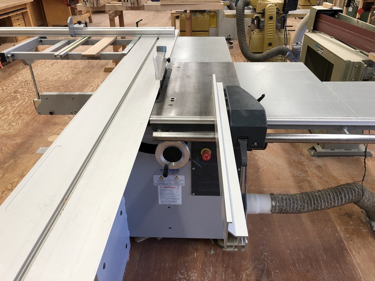
Sliding table top
The sliding table varies in length depending on the saw. It is machined from aluminum, and has a ‘T’ mitre slot along its length for receiving hold-downs and jigs. The table slides on a chassis (attached to the main body of the saw) on roller bearings. A lock on the sliding table allows it to remain motionless while sheet goods are loaded on and positioned against the fence. It is common for the sliding table to be set about 10 thousandth of an inch higher than the main table to reduce friction and drag on the part being cut.
Crosscut fence and outrigger table
An aluminum crosscut fence is attached to the sliding table. The fence has a measuring tape similar to the rip fence for accurate measurements with the flip stops. Some crosscut fences have a telescoping feature that supports the work and the stop, allowing long lengths to be cut. The fence holds one or two flip stops, which make it possible to square an end on multiple parts and cut them to length. They move up out of the way of the crosscut fence when not in use.
Panel saws have an outrigger table that attaches to the sliding table and is supported by the outrigger. This table extends under the crosscut fence to support large work pieces, while the outrigger prevents the table from sagging. On most saws, the table can be positioned at any point along the length of the sliding table. When crosscutting smaller pieces, it is sometimes desirable to have the fence/outrigger table assembly near the midpoint of the sliding table so less of it is projecting out the back of the saw.
The crosscut fence uses positive stops to keep it at 90° to the blade. These may need to be calibrated periodically. The crosscut fence may also be positioned at an angle. On most saws, there is a pivot point where the fence bolts nearest the saw blade. To angle the fence, loosen the lock bolts, pivot the fence and re-tighten the locking mechanism to the outrigger table. While the table may have an angle indicator, it is best to use a more reliable method of setting the fence. Always check that the table is cutting square when you return it to 90° by using a reliable square and making a test cut.
The sliding panel saw is unique from the table saw in that the crosscut fence is usually positioned on the far side of the material being cut. The stock must be held tightly against the fence as the force of the blade is acting to push it forward. The fence is positioned this way so that large sheets can be slid onto the table without having to clear the crosscut fence. On a sliding table saw, using the outrigger table and crosscut fence is the ideal position for the workpiece and the place where most of the cutting happens.
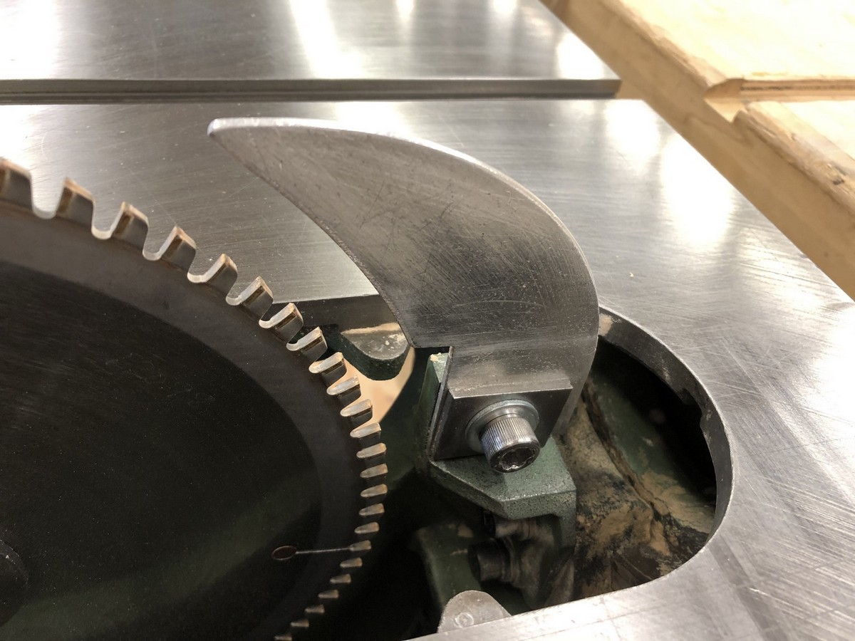
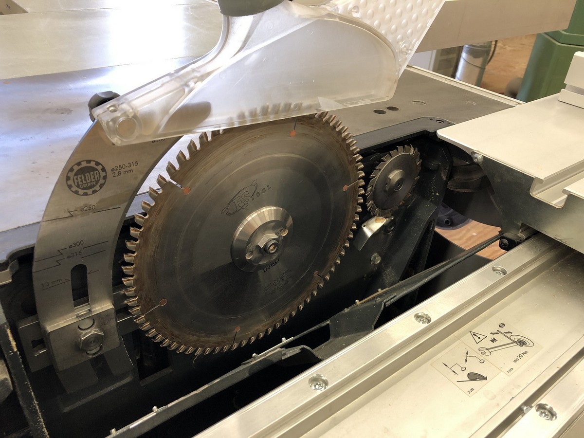
Scoring blade
As panel saws are used to cut veneered and melamine panels, they have a scoring blade unit that serves to reduce tear-out and chipping on these delicate materials. The scoring blade is located directly in front of the main blade. It is used for cutting sheet goods only, and can be lowered below the table when not in use.
The scoring blade is set slightly above the main table, and rotates in a direction opposite the main saw blade. Its width must be carefully calibrated to the kerf of the saw blade; if it is too narrow it will not prevent chipping, if it is too wide the panel will be overcut. To achieve a perfect width, scoring blades are manufactured to be adjustable. They are comprised of two outside blades and some means to space them apart, either by thin metal shims (similar to dado shims) or by a dial mechanism.
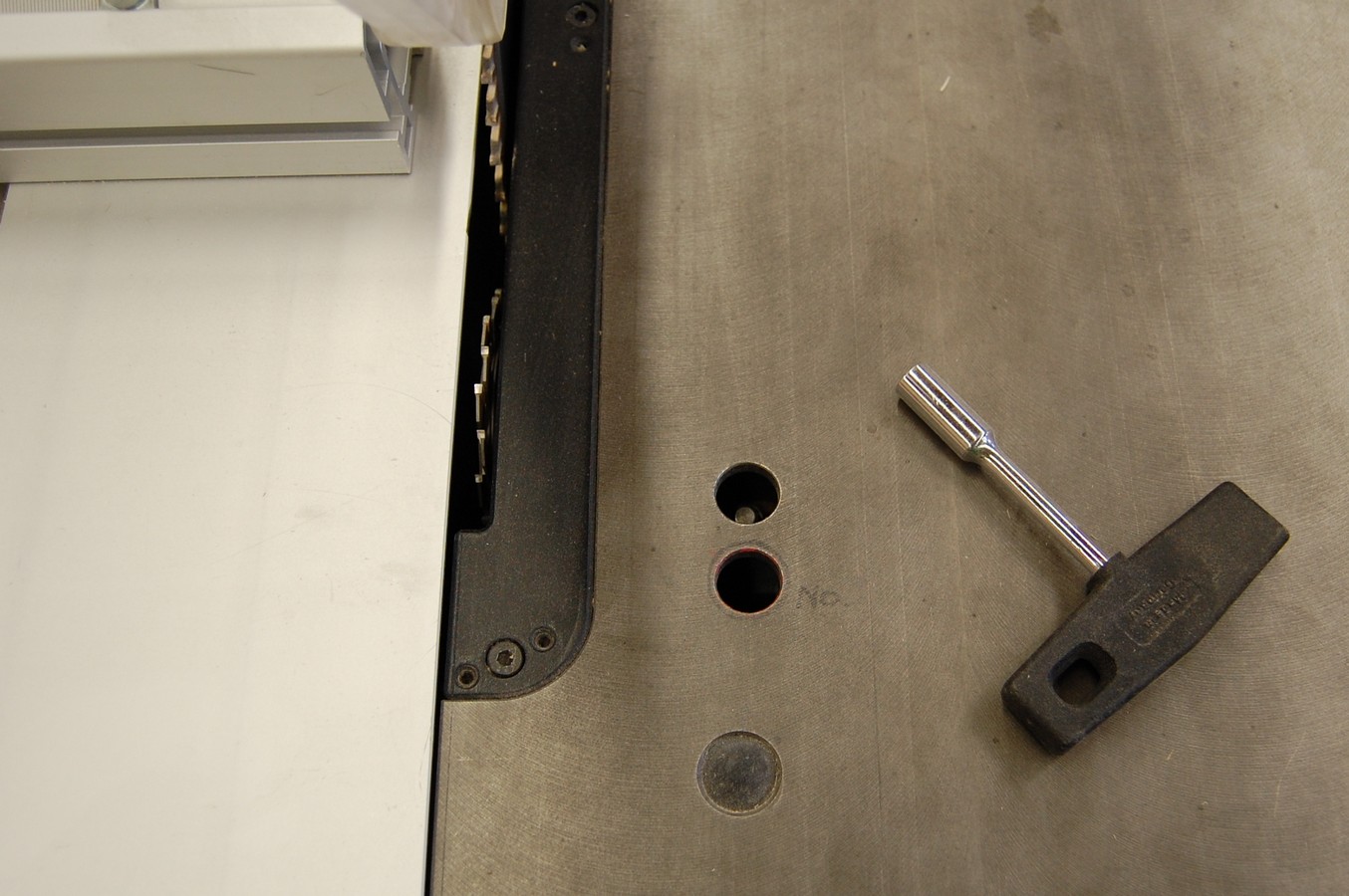
In addition to an adjustment for height, scoring blades have a provision for lateral adjustment. This adjustment is used to ensure they are cutting centered in the kerf of the main blade. Both lateral and height adjustments are made from an access point in the top of the main table. Whenever the blades are sharpened or are changed, both the kerf width and lateral alignment of the scoring unit must be checked and recalibrated.
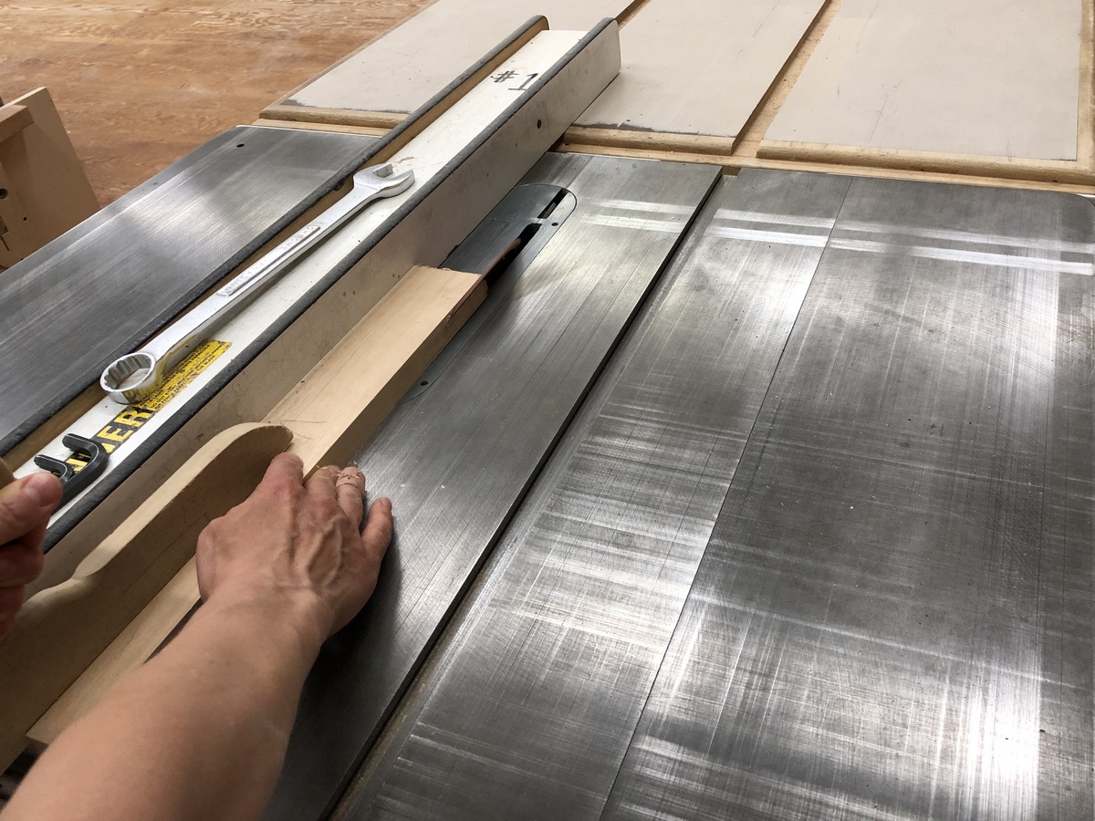
To check and recalibrate:
- Turn on the saw, including the scoring blade. Run a scrap of veneered plywood into the saw until the main saw begins cutting.
- While holding the workpiece securely on the table, shut off the saw and wait until it comes to a complete stop.
- Remove and inspect the piece. The kerfs of both blades should be perfectly aligned and there should be no tear-out or overcutting.
- If the scoring cut is cutting past the kerf of the main blade on one side, use the lateral adjustment to move it in the desired direction. It is accessed through the top of the saw table. Re-check by making another test cut.
- If the scoring cut appears centered in the main blade kerf, but is cutting past it on both sides, the scoring blade kerf is too wide. Depending on the type of scoring blade, adjust the width of cut by removing shims or adjusting the dial and re-check.
- If it is centered but undercutting, it is too narrow. Adjust the width of cut and re-check.
