6 Parts of the Jointer
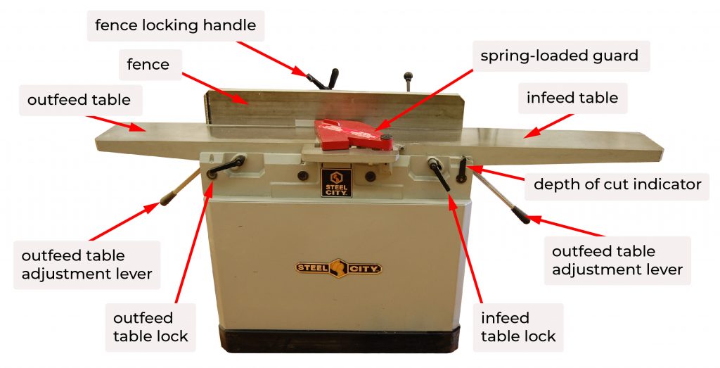
Infeed table
The infeed table supports the workpiece as it passes over the cutterhead. Both the infeed and outfeed tables are made of cast iron, and should be dead flat and parallel to each other. They move in relation to the cutterhead, which is fixed to the base. The position of the infeed table relative to the cutterhead determines the depth of cut. The lower the table below the cutterhead, the greater the depth of cut.
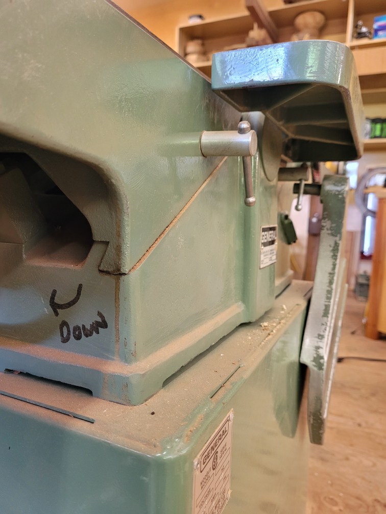
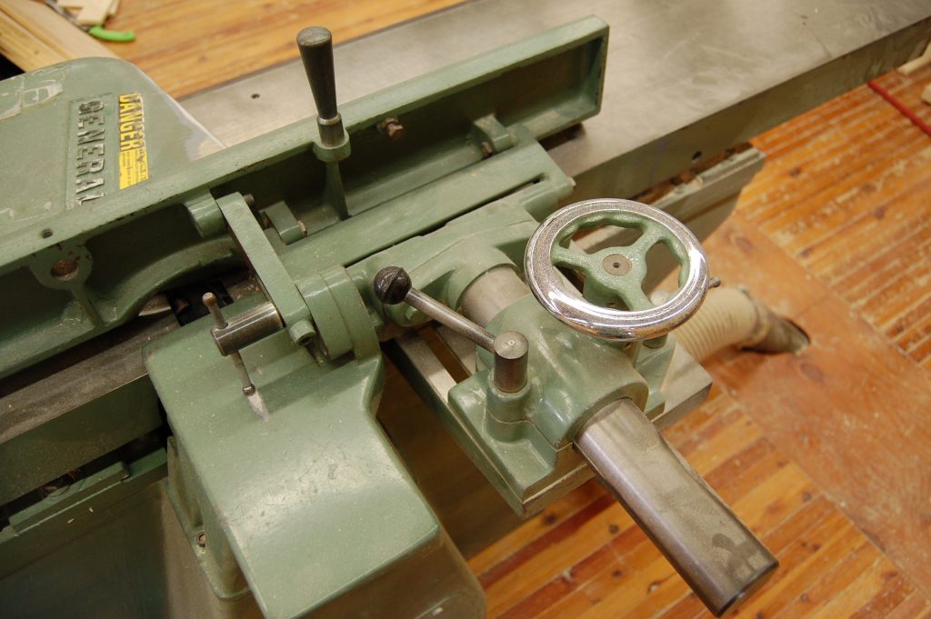
Infeed table height adjustment
The infeed table height adjustment is made via a handwheel or a lever, depending on how the tables are designed to move. The table should be locked after the height is set, usually with a ‘T’ handle.
Depth of cut indicator
Most jointers have a depth of cut indicator, consisting of a gauge and pointer. They are not very accurate, and need to be calibrated every time straight knives are changed. Use these as a rough estimate only. If the depth of cut is critical, run a piece of scrap wood about 50 mm into the cutterhead, then carefully pull it back out of the cut. The gap between the bed and the workpiece is the exact depth of cut. Alternately, lock out the machine and place a straight edge on the outfeed table. The difference in height between the infeed and outfeed table is the depth of cut.
Outfeed table
The outfeed table supports the just-machined surface as it clears the cutterhead. Its position relative to the cutterhead must be set perfectly for the jointer to function properly.
Outfeed table height adjustment
The outfeed table is adjusted in the same manner as the infeed table. The outfeed table should only be adjusted when the knives or cutters are being changed, or if the jointer is not cutting properly. Ensure the outfeed table is securely locked to the base once it has been adjusted.
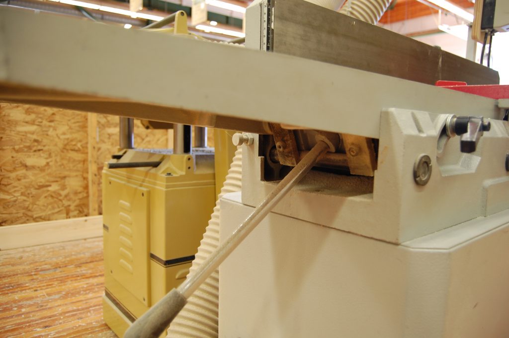
Dovetail ways or pivoting arms
The tables are fixed to the base by means of dovetail ways or pivoting arms. On a machine with dovetail ways, the base casting has a sloped surface with a precision machined dovetail shaped casting. The table is likewise machined with the matching profile. The two halves slide together in direct contact, and should be set up to have very little play between the base casing and tables. This allows the tables to move, but keeps things in alignment.
Many European jointers uses a system of pivoting, parallel arms to connect the base to the tables. In both cases, the alignment between the tables and the base must be exact for the jointer to perform perfectly. Refer to the machine’s manual if adjustment is required to bring the tables and base into alignment.
Fence
The jointer fence is used to keep the workpiece in position as it is fed through the machine. There are two main adjustments on the fence, lock and tilt. Different makes of jointers use varying fence systems, they all have the same basic adjustments.
Fence lock
The fence may be moved laterally across the table and locked in place at any point along the length of the cutterhead. When narrow stock is being jointed, it is desirable to position the fence near the operator to reduce the need to lean over the machine. Occasionally, the knives may have minor nicks that leave tracks in the machined surfaces, the fence can be placed to avoid these areas.
Fence tilt
This adjusts the angle of the fence relative to the tables. This is the adjustment for square, and to tilt the fence for cutting bevels. Many jointers have a positive stop for 90°, this should be checked for accuracy periodically. Use an engineer’s square placed on the outfeed table just past the cutterhead. Always check by cutting a test piece before proceeding.
Another way of confirming the machine is cutting square is to edge joint two pieces. With the faces that were against the fence laying flat on the machine table, the edges should line up perfectly.
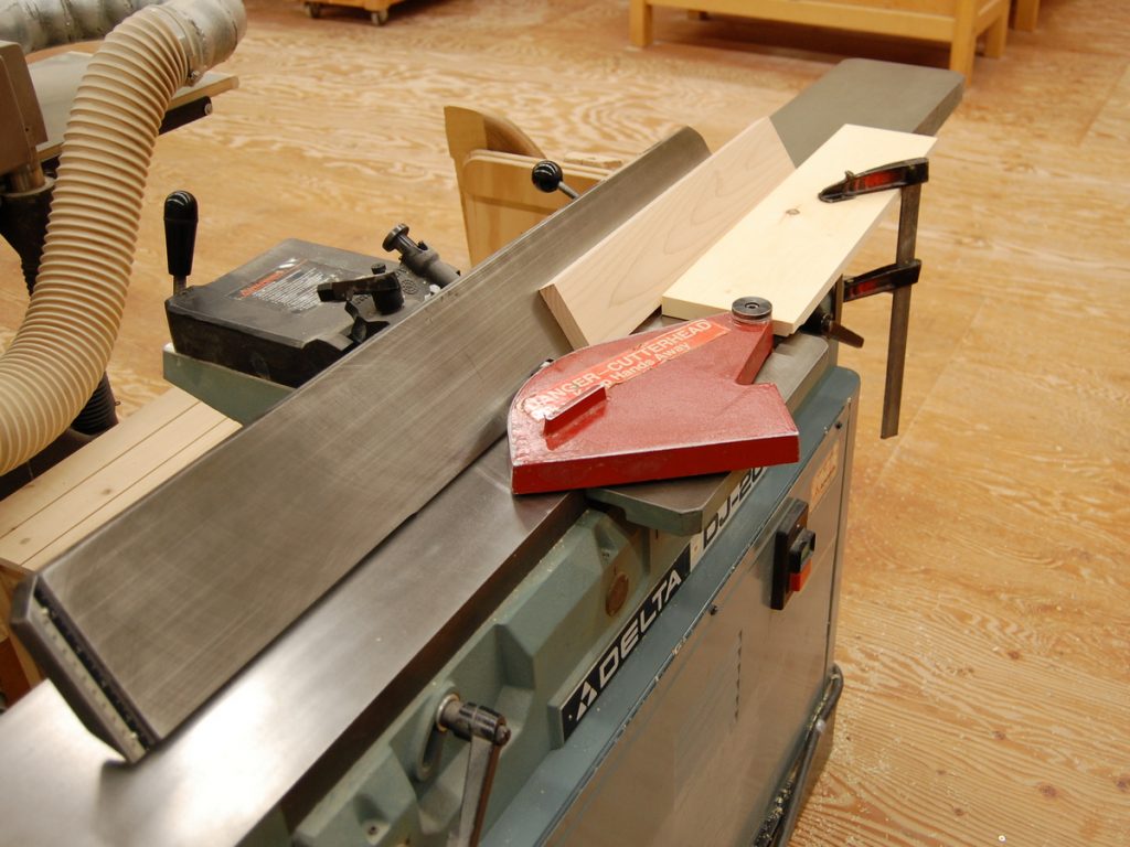
Guard
The guard should be used at all times unless a specific operation, such as rabbeting, necessitates its removal. Guards should have a return spring to ensure they cover the entire cutterhead as soon as the workpiece clears the cutter. If the guard does not return quickly to cover the cutterhead, inspect the mechanism and adjust the spring as required.
Rabbeting ledge and arm
If the jointer has a rectangular recess in the table castings, the jointer can be used to cut rabbets. The spring loaded guard must first be removed. The knives must be set just past the rabbeting ledge to allow them to cut properly, and to allow the stock to remain tight to the fence throughout the cut. If they are set back from the rabbeting ledge, the stock will come away from the fence as it makes contact with the outfeed table. The ends of the knives should have a slight relief angle ground on them to allow for efficient cutting, and to prevent burning on the workpiece from friction.
The rabbeting arm is an extension that bolts to the left side of the infeed table. It supports wide work pieces while rabbeting the face of a board.
Dust chute
The chips generated by the cutterhead are directed out of the machine by the dust chute. This chute is part of the machine base, and usually terminates in a housing for dust collection. On small, hobbyist machines, there may not be dust collection in which case the debris piles up on the floor.
From time to time, the chute may become clogged with chips. You will know it is clogged if chips are coming back out of the cutterhead onto the infeed table as you are jointing. To clear the blockage, lock the machine out and confirm by pressing the start switch. Remove the dust collection port, and use your hand or a short stick to pull the chips out of the machine.
Push Block
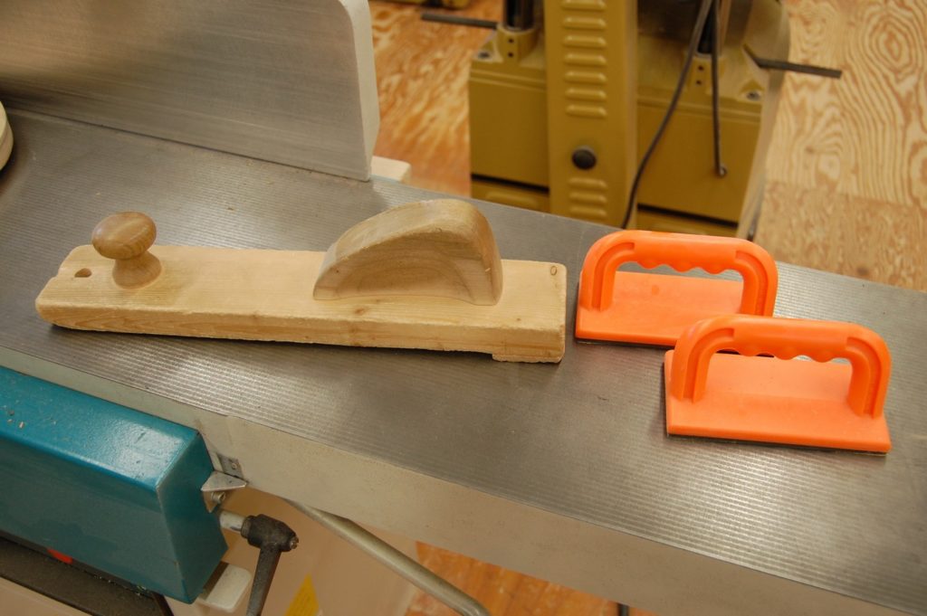
Not a part of the jointer, but integral to its safe use is a push block. When face jointing, the distance from the knives to the face of the workpiece is too small to complete the cut while pushing by hand, and it would require passing your hands directly over the cutterhead. A push stick of the type used on the table saw can work, however more effective is a shop-made push block designed for the jointer. The block is long and flat, with a handle at the rear and knob at the front. The back bottom end has a thin strip of wood glued to the push block for hooking on the workpiece and moving it though the cut. Fasteners should not be used to attach the strip to the block as it may come into contact with the cutter when jointing thin stock and damage the knives. The block is long so that it may be used to safely hold down and guide thin and short work pieces without the operator being near the cutterhead.
Commercial foam-backed push blocks are also useful on the jointer. They can be used in conjunction with the push block described above for jointing longer stock.
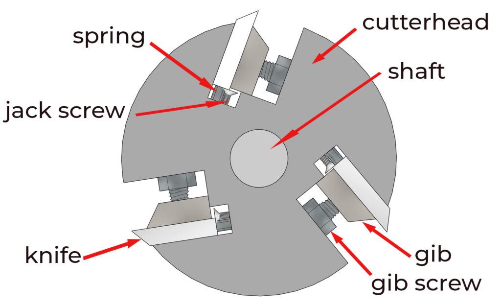
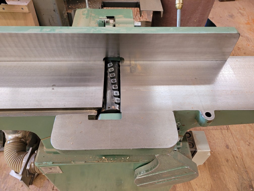
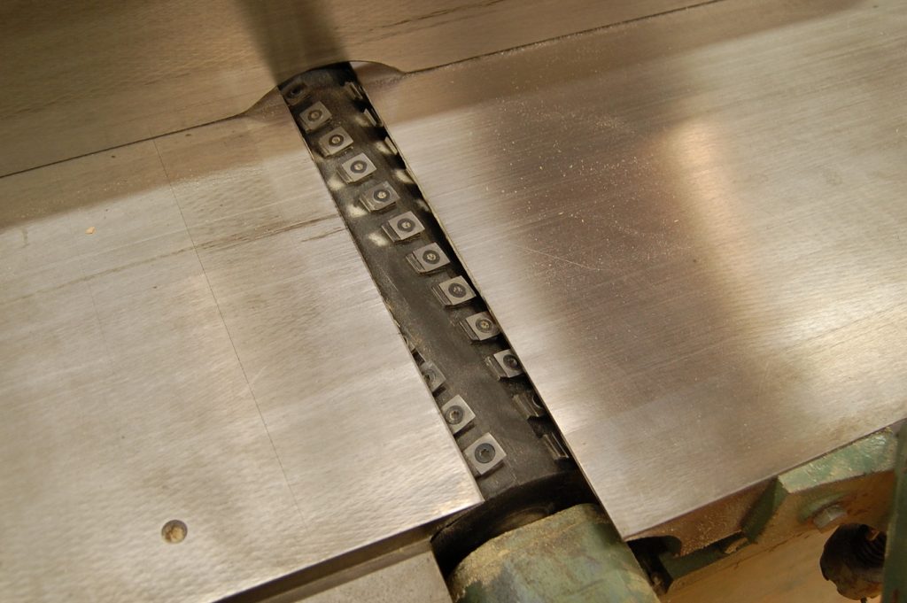
Cutterhead
The cutterhead is a precision machined cylinder that is secured to the base casting and rotates via bearings. The cutterhead can have between two and four straight knives, or many carbide cutters if the cutterhead is helical with inserts.
The size of the jointer is denoted by the length of the cutterhead. If the capacity of the machine allows it to face joint an 8″ board, it is an eight inch jointer. Jointers are commonly available in sizes ranging from 6″ to 20″, with 8″ and 12″ being the most common.
The cutterhead is usually driven using a pulley and belt arrangement. Some older machines use a direct drive, where the motor is directly mounted to the shaft of the cutterhead.
Gibs
Most straight knives are held securely in the cutterhead with gibs. The gib is a metal bar that retains the knife in the cutterhead by applying pressure to the knife, forcing it against the slot in the cutterhead. The gibbs are removed to change the knives. Inspect and clean them of any residue before reinstalling them.
Gib screws
The gibs have threaded holes for gib screws. These machine screws have square heads that are slightly relieved on the top. As the screw is backed out of the gib, the head tightens against the machined slot in the cutterhead.
The slot in the cutterhead is narrower at the top (where the cutting edge of the knife protrudes) than at the bottom. This creates a dovetail shape that counteracts the centrifugal force acting on the knives as the head rotates.
Jack screws or springs
When the knives are changed, they must be set at exactly the same height. To assist in leveling the knives, a small adjustment screw is located under the bottom edge of the knife at either end of the cutterhead. The screw may be turned in minute increments to get the knives perfectly adjusted.
Some jointers instead use a small spring in the same location. A block of wood set on the outfeed table keeps tension on the knives as the spring pushes them up. The gib screws may then be tightened.