15 Parts of the Band Saw
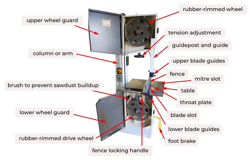
Drive wheel
The lower wheel is connected to the motor with a belt and pulley to power the band saw. Both the drive and upper wheels are slightly crowned, which keeps the blade running true and helps to keep it from running off the wheel. The wheels have a hard rubber tire that covers the surface that the blade contacts. The tire provides some cushion between the metal surfaces and prevents damage to both. When the blade breaks during operation, shut the machine off as quickly as possible to prevent the blade from damaging the tires.
Upper wheel
The upper wheel is an idler wheel, meaning it is not powered but spins when the tensioned blade is being driven by the lower wheel. The upper wheel can be raised and lowered as well as tilted. These adjustments allow for changing and tensioning the blade as well as tracking.
Column or arm
Every part of the bandsaw above the table is attached to the column. It provides rigidity to the machine between the two wheels. The blade travels up the front of the column which had a guard to cover it.
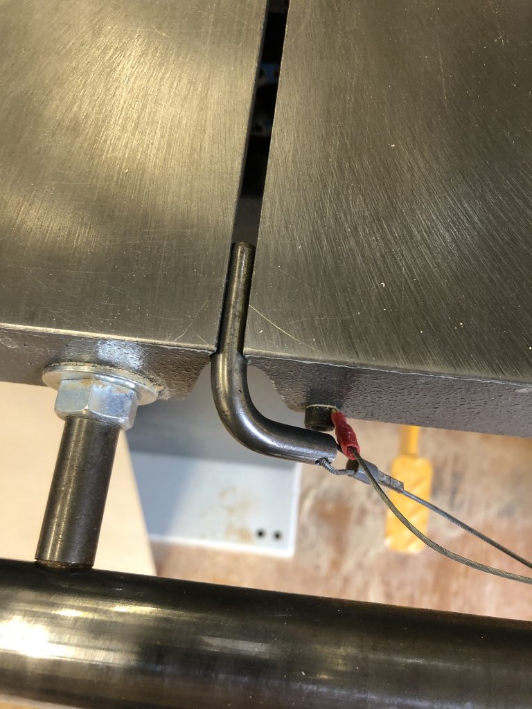
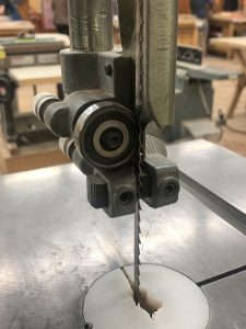
Table, blade slot
The table is made of cast iron, and should be flat and true. Many band saws have a mitre slot machined into the table for use with a mitre gauge, the slot can also be used to secure various jigs and hold downs such as featherboards. In order to change the blade, the table must have a slot to allow it to be positioned in the centre. A removable round pin is used to keep the halves of the table in alignment. It should be kept in position unless the blade is being changed.
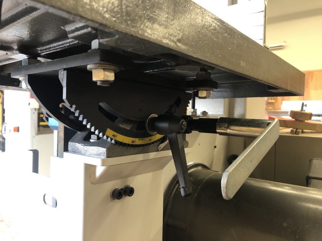
Squaring and tilt adjustment
The table is attached to a trunnion assembly that is secured to the band saw cabinet or casting. The mechanism is located directly underneath the table, and is usually secured with a ‘T’ handle. The table may be tilted for cutting bevels and angles, the same adjustment is used to square the table with the blade. The table-tilt mechanism allows you to tilt the table from 0 – 45°. and has a positive stop at 90°. Because the blades are flexible and every blade will sit in a slightly different position on the tire, the table should be checked for square every time the blade is changed.
Motor and drive belts
Depending on the saw, the motor may be exposed or housed in the saw cabinet. The dive belts should always be guarded for safety. Some machines (especially larger ones) may have more than one belt to prevent slippage and transfer more power to the wheel. Larger saws and motors may also have a soft start, meaning they take a few seconds ramping up to full speed. This reduces strain on the motor and the connected machine parts. Always allow any electric motor with a soft start to come up to full speed before applying any load.
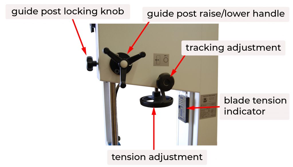
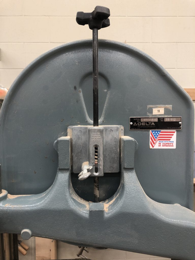
Tension control
The upper wheel is designed to move vertically in order to apply tension the blade. Tension is exerted via a strong spring, the adjustment is usually controlled via a handwheel located directly above or below the upper wheel. In order to change the blade, the top wheel is lowered, removing the tension on the blade to the degree that the blade is slack on the wheels. Most bandsaws have a scale that indicates the tension, however they are usually not accurate. Most indicate a tension that is above the actual tension being exerted on the blade. See set up and maintenance for proper tensioning of band saw blades.
Tracking control
The upper wheel can be canted forward and backward to keep the blade running in the centre of the wheels. It is necessary to check the tracking every time the blade is changed, and adjust if necessary.
Blade Guide Mechanism
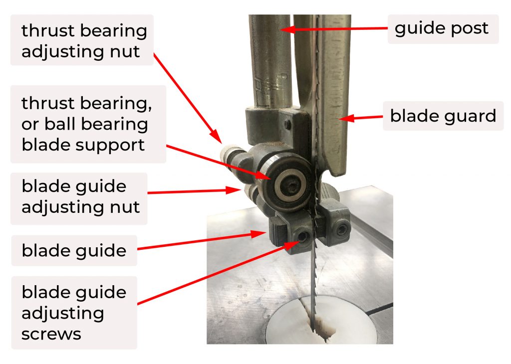
Guide Post
The guide post is a height adjustable assembly that guards the blade above the table, and is the mounting location for the upper guide assembly. The guide post is adjustable for different thicknesses of material by raising and lowering it. It should be adjusted so the guides clear the material being cut by about 6 mm or 1/4″. If the guide post is not adjusted and set much higher above the workpiece, the guides are not able to support the blade as well and the cut may not be as accurate. The guide post also has a guard that covers the blade and should always be positioned properly for safe operation.
Blade guards
The band saw is guarded at all points except the area between the table and the guides. Ensure the guide post which includes a guard is adjusted to the correct height above the workpiece. The wheel guards are hinged to allow access to the interior of the machine for maintenance and changing the blade.
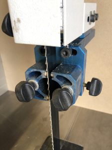
Blade guides
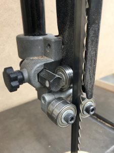
Band saws have two sets of guides, one above and one below the table. Each set consists of three individual guides: one that supports and limits travel at the back of the blade, and one on either side.
As material is fed into the blade, the force exerted acts to push the blade backwards and off the wheels. The rear support is known as the thrust bearing or blade support bearing. It is most often a ball bearing mounted just off-centre to the blade. The thrust bearing is adjustable front to back to account for different blade thicknesses. When the saw is running but not under load, the blade should not make the bearing spin. As soon as the cut engages, the blade should cause the bearing should spin. This extends the life of the bearing as it is only turning when wood is being cut.
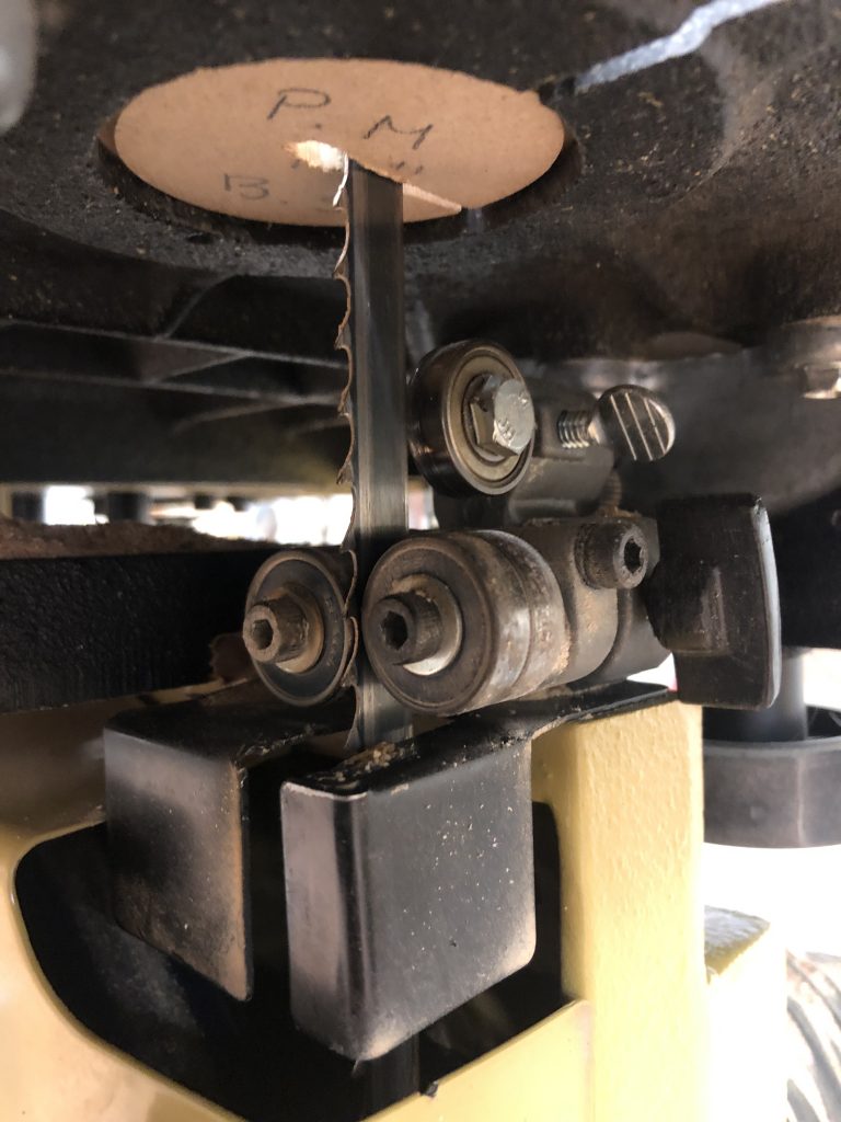
There are several different types of side guides. The most common are bearings and guide blocks. Both support the side of the blade, and should be adjusted to provide minimal clearance. A sheet of paper is about the clearance required. The guides should be set back far enough that the teeth clear the guides. A third type of guide uses small ceramic blocks that can be set with the blade just-touching them. They are low friction, resulting in cooler running blades. They are extremely long-lasting in comparison to standard ball bearings.
A rotational bearing comprising a rotating arc or ring sliding in the groove of a stationary arc, used in machinery to allow a workpiece to be moved relative to a fixed tool.
