11 Parts of the Planer
This video is specific to the model at BCIT, but the parts, operation, and safety rules are the same. Note the minimum length that can be safely machined depends on the model of planer.
The planer is more complex than the jointer in terms of parts, but easier to use once the mechanics are understood. Unlike the jointer and table saw, the planer has a mechanism that self feeds the work though the machine, increasing its complexity.
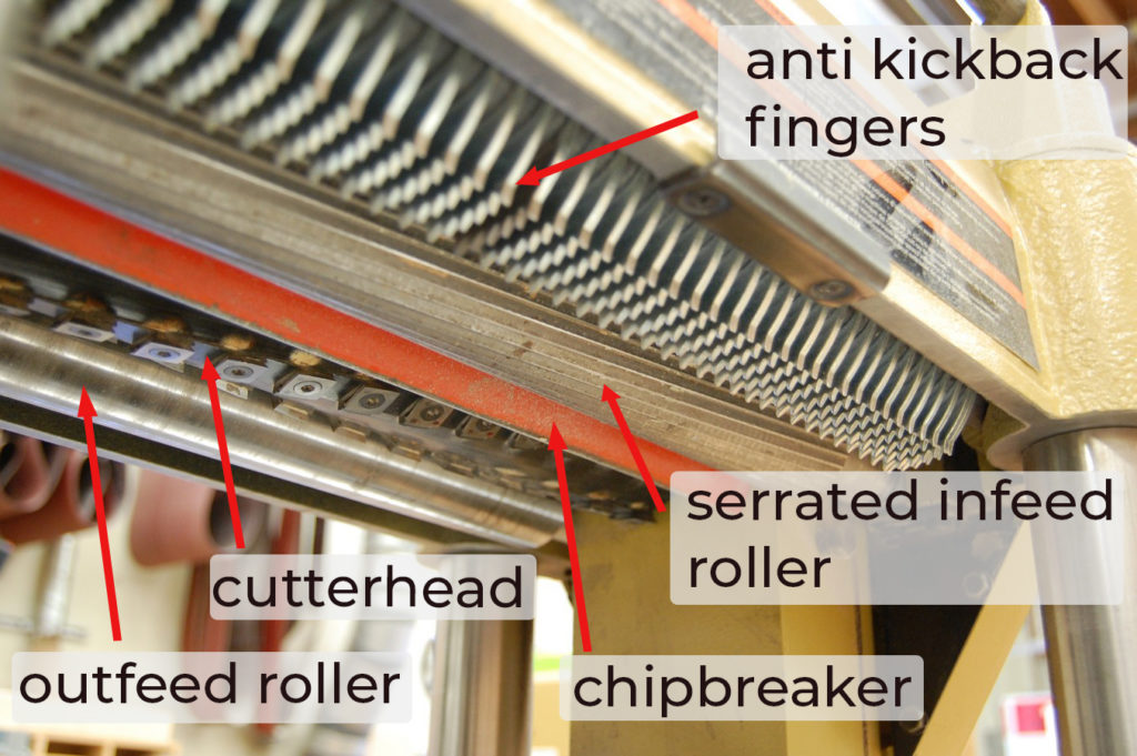
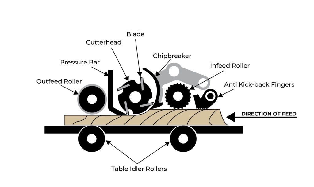
Cutterhead
The thickness planer cutterhead and tooling is nearly identical in design to the jointer cutterhead. It may have straight knives, disposable, or carbide insert tooling. The size of the planer is denoted by the length of the cutterhead. Another measure of planer capacity is the maximum height above the table the cutterhead can travel. This determines the maximum thickness of stock that can be fed through the machine.
Infeed rollers
The infeed rollers are powered to grip and push the material into the machine while keeping it tight to the table. They are spring loaded to allow the material to pass underneath. The tension on the rollers is adjustable.
On some machines, the feed rate can be adjusted by changing the RPM of the rollers. There are three types of infeed rollers, all perform differently.
Smooth
Smooth rollers with a neoprene covering are found on small portable planers and some light industrial planers. Because they are smooth, they grip the wood without leaving any marks or defects in the surface. Planers with smooth infeed rollers excel at taking light finishing cuts. The infeed roller is a single cylinder that is parallel to the machine table, which can have some disadvantages when feeding multiple parts of different thicknesses at the same time. The one piece roller tends to feed the thicker stock while thinner pieces stall in the machine from lack of down and feed pressure.
Serrated
Serrated infeed rollers are commonly found on larger planers. They have grooves or serrations machined into the steel cylinder to grip and feed the material through the cutterhead. Machines with serrated infeed rollers are capable of taking heavier passes, and at higher feed rates. However, the serrations will leave marks on the surface if the depth of cut is less than the bite of the serrations. If the infeed roller is leaving serrations at a moderate depth of cut, the tension may be too high and can be adjusted.
Segmented
On larger industrial planers, the serrated infeed roller is broken up into smaller sections, or segments. Each segment is spring loaded and can move up and down independently. This allows material of different thicknesses to be planed at the same time without the tendency of the thinner pieces to become stalled in the machine. It is more efficient as stock of varying thicknesses can be fed at the same time.
Outfeed rollers
The outfeed rollers are also powered to help feed the stock and exit it from the planer while keeping it tight to the machine table. Outfeed rollers are always a single cylinder as the material that exits the machine is a consistent thickness, and there is no need for segmentation. The rollers are smooth to prevent marring the finished surface. Planers with neoprene infeed rollers will also have neoprene outfeed rollers; planers with serrated infeed rollers will have smooth steel outfeed rollers.
Pressure bar
The spring loaded pressure bar is located just past the cutterhead as close as is safely possible on the outfeed side. It applies pressure on the wood to prevent it from rising up and being overcut by the knives. This tendency to overcut or snipe occurs as the end of the board is no longer held down by the infeed roller.
Chip breaker
The chip breaker in a planer functions much the same way a chip breaker in a hand plane does. It presses on the surface of the material just ahead of the cut, forcing the wood fibers being cut to break off in small pieces instead of long slivers, preventing tear out. Small portable planers do not have chip breakers, they rely on high cutterhead speed, low feed speed and small depth of cut to limit tear-out.
Anti-kickback fingers
Anti-kickback fingers are located just before the stock engages the infeed roller. They move freely up and out of the way of the workpiece in the forward direction, but prevent the stock from being backed out of the planer, preventing kickback. Occasionally, a workpiece gets jammed in the planer and it is necessary to lower the table to clear the fingers and remove the piece.
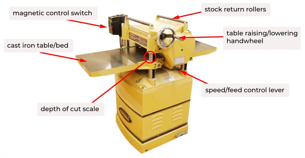
Table bed
The table bed is a single surface that is perfectly flat. On small portable planers, it is usually made of sheet metal which lessens the weight of the machine, on stationary planers the table bed is cast iron. In portable planers, the table is fixed while the cutterhead moves to adjust the depth of cut, in stationary planers the table moves while the cutterhead is fixed. The table bed should be kept clean and waxed to reduce friction and allow stock to move easily. Some planers have an extension off the main tables to increase the surface area. It may be a frame with rollers or solid cast iron. Caution must be exercised when working on a planer with extension table rollers as there is a greater possibility of catching clothing or hands in the space between the rollers and the stock.
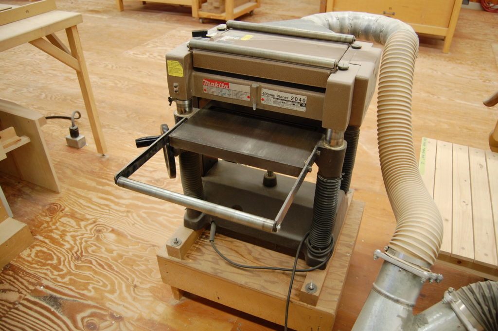
Table or idler rollers
To allow the stock to travel through the planer while still being held firmly down to the table, the table has two rollers located directly under the infeed and outfeed rollers. They are set just higher than the table surface to reduce friction and drag. They should be kept clean and free of pitch and residue.
Idler rollers can be a cause of sniping if they are set too high above the table. If sniping occurs, try lowering the rollers as far as possible while still keeping them in contact with the workpiece.
Height adjustment
Many stationary planers use a handwheel to engage a lead screw that adjusts the depth of cut. Small portable planers may use a knob or hand crank. Large industrial planers often have a powered height adjustment. The height adjustment should always be in the forward advancing position (moving from thick to thin) on the final pass to prevent backlash in the screw mechanism resulting in table movement. The depth of cut should be locked on the final pass.
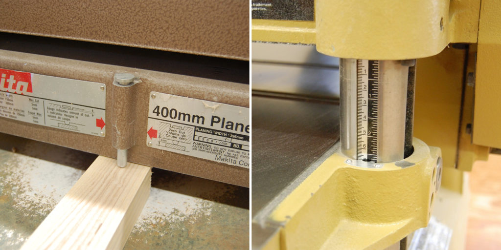
Depth of cut gauge
On many planers, a scale and pointer is used to indicate depth of cut. It should be used as a guide only. The most reliable means of confirming is by measuring a piece that has passed through the planer. When changing the knives in a straight knife cutterhead, always recalibrate the gauge.
Some planers have a type of gauge that reads directly off the surface of the workpiece to show the depth of cut. Others have a limiter on the infeed side that will not allow material that is too thick to be planed.
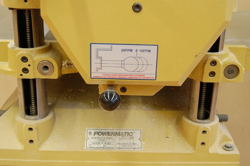
Feed speed control
Many stationary planers have a control for the feed rate. This is usually indicated in feet per minute. A slower feed rate will give a higher quality cut. If multiple passes are needed to bring the stock to final size, the feed rate can be set higher on the initial passes, then reduced for the final pass.