5 Set Up and Maintenance
All machines require set up to achieve accurate and repeatable results, and maintenance to keep them working properly. The following information will guide you through these tasks. Learning to properly set up and tune the machinery you use on a daily basis is important in keeping the entire shop efficient and productive.
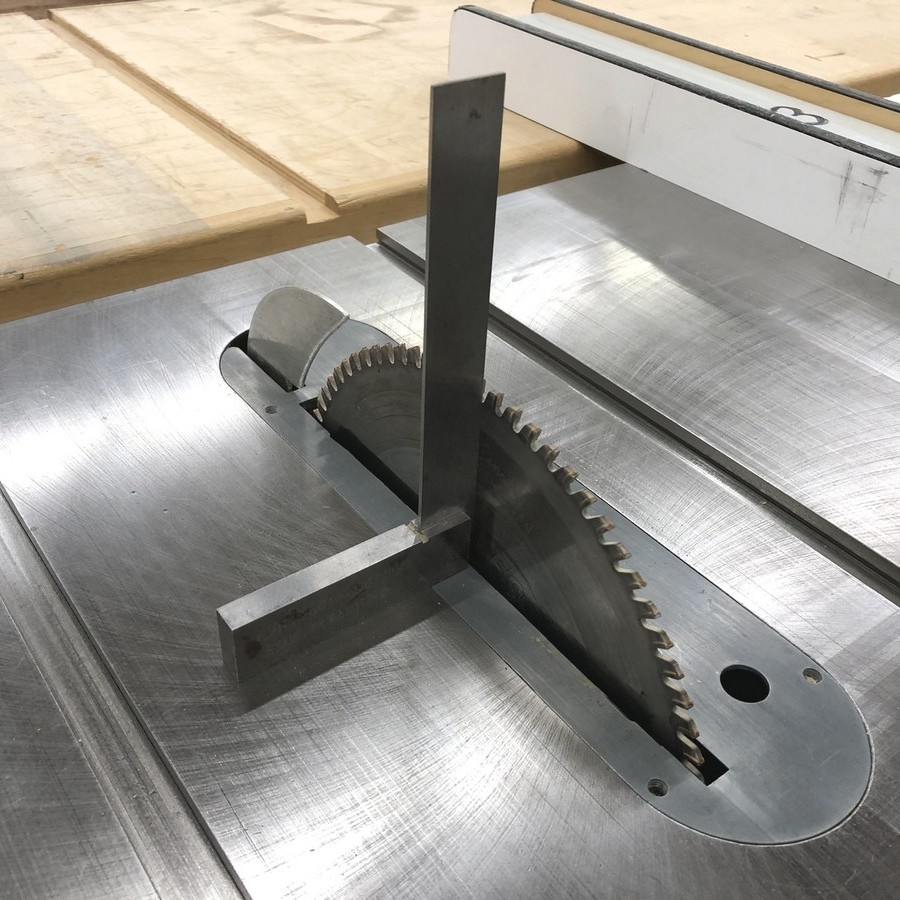
Setting the blade to 90° to the table
One method to set and check the blade for square is to use a reliable engineer’s square. Raise the blade out of the table at least 50 mm or 2″. The greater the height of the blade out of the table, the more accurate the reading will be. With the throat plate in place, set the square on the table on the side of the blade that is closer to the table. This allows for the best support of the square on the table reference surface. Make sure the square is roughly centred and perpendicular to the blade. Gently slide the square up to the plate of the saw blade, ensuring it makes contact between and not on the carbide teeth. Standing directly in front of the blade, look for light showing between the square and the blade. If there is light the blade is not square, use the tilt handwheel to bring the blade into alignment with the square. It is always advisable to make a test cut to confirm. A sliding T bevel can be used in the same manner to set accurate angles.
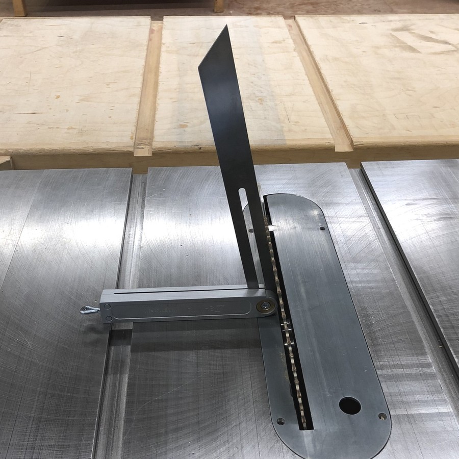
Setting the mitre gauge to 45° or 90° to the blade
While many mitre gauges have a positive stop for both 45° and 90°, it is necessary to confirm them for accuracy. Using a large 45° drafting set square, place the square against the fence of the mitre gauge and gently bring it into contact with the blade. The blade should be fully raised out of the table to begin, and rotated as needed to ensure the set square is contacting the plate of the blade only, not the carbide teeth. If the set square contacts the blade along its length, the gauge is set. Depending on the type of blade used, it can be difficult to rotate the blade to a position where just the plate makes contact, in this case the blade can be rotated so the set square makes contact with the saw teeth only. If adjustments are required, make them and then adjust the 45° and 90° positive stop on the miter gauge to recalibrate it for future use. This adjustment will be slightly different depending on the brand of mitre gauge, it is usually done by adjusting a small set or Allen screw on the stop.
The only reliable way of checking if the machine is accurately set to 90° or any other angle is by making test cuts. This is especially important when setting up to cut any mitres. Use a piece of scrap to mitre four pieces into a square to confirm the corners are perfect. It is worth the time and effort.
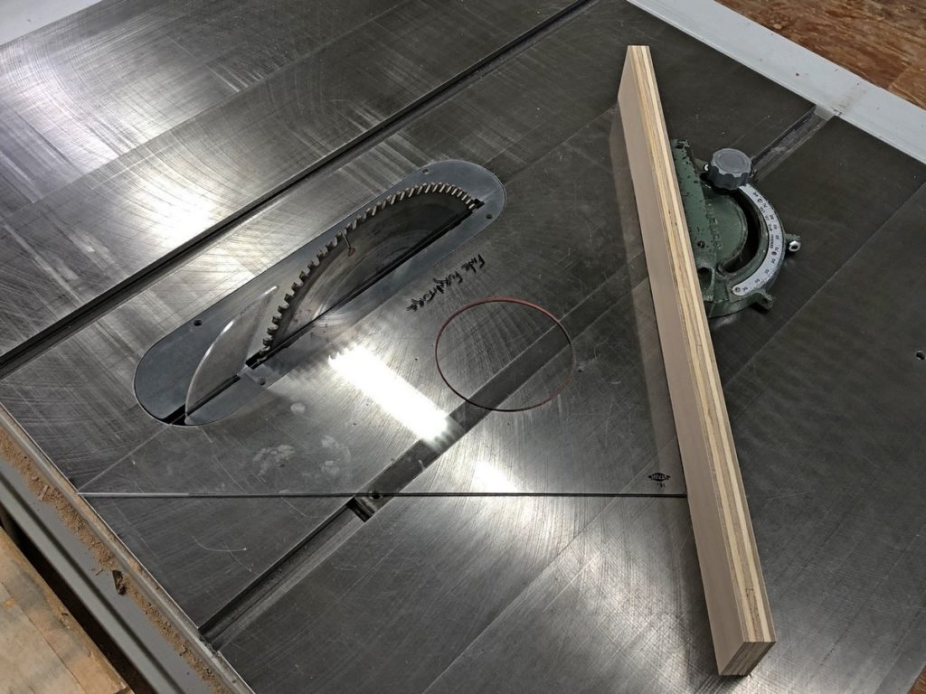
Rip Fence Calibration
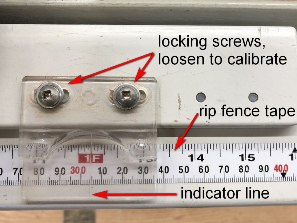
Constant parallel fences all come with a measuring tape built on to the fence rail. They should be checked periodically for accuracy. Once a blade is installed on the saw a test cut is made through a scrap piece of wood run along the fence. The freshly sawn scrap is then carefully measured and the fence calibrated to the exact measurement. On a ‘T’ style fence this is achieved with the adjustable cursor, a piece of clear plastic with an inscribed indicator line. A European style fence reads directly off the face of the rip fence, calibration is made by loosening the tape and adjusting it as needed.
Once the fence has been calibrated in this manner, it can be reliably set without switching the motor off and waiting for the blade to stop turning before a new setting can be measured. Being able to trust the fence setting is essential for accurate and efficient operation, and reduces wear on the electrical parts of the saw as it isn’t being switched off and on repeatedly.
It is important to note with modern left-tilt table saws that when the saw blade is installed, it references the left side of the saw blade against the arbor washer. Because the rip fence is to the right of the blade, changing between thin kerf (3/32″) and standard saw blades (1/8″) will throw off the calibration of the rip fence depending on what thickness of blade was installed in the saw when the fence was calibrated.
Cleaning & dressing the table
Over time, machine tables get dirty and may accumulate small amounts of pitch and other contaminants. This increases friction, which requires the operator to apply more force to feed the work. Occasionally, the cast iron table may get small burrs and nicks, usually as a result of metal objects such as staples, brads or screws coming into contact with the table. These can scratch and catch on the workpiece.
To dress the table and remove any burrs and nicks, use a smooth, flat file to remove them. Keep the file flat on the table with light pressure while sliding it forward. This is usually sufficient to remove them.
To clean the table, use 400x silicon carbide wet-dry sandpaper or steel wool, adding mineral spirits as a cleaner and lubricant. Wet sand the entire surface, then wipe the solvent and grime away with a dry cloth. Apply a thin coating of paste wax, let dry then buff with a dry cloth. Wax the rip fence as well. It is usually necessary to clean and wax the table after machining a quantity of wet wood, such as construction lumber, or lumber that is particularly pitchy, such as pine. Cast iron rusts easily, and any moisture will quickly create a rough surface. The addition of paste wax also helps to prevent moisture from damaging the table. After dressing the table, it is noticeably easier to feed material through the saw. This maintenance should be performed monthly or as required.
Cleaning and lubricating height and bevel adjustments
Fine sawdust and pitch residue can quickly build up on the moving parts of the saw. This creates friction and resistance in the screw that controls the height and bevel, making it difficult to move the adjusting handwheels.
To clean these parts, lock out the saw and open the cabinet to access the mechanism. Using a vacuum, remove the dust from the leadscrews and surrounding parts, then finish with compressed air. It is advisable to have the dust collection on and wear PPE such as an approved respirator or dust mask as this creates fine particulate. If the leadscrew is packed with dust, contaminated with pitch or is excessively dirty, a soft brass wire brush may be used to remove the material.
Because space is limited, it can be difficult to access the necessary parts. You will need to adjust the height and bevel to get to the leadscrew. In some cases, you can access the mechanisms from the cut-out in the front of the cabinet where the bevel scale is, and from the throat opening in the table with the blade removed. At the same time you clean and lubricate the height and bevel leadscrews, lubricate the trunnions at the front and back of the saw.
Do not use machine oil or a product such as WD-40™ as a lubricant as it attracts excessive amounts of dust and quickly become loaded with sawdust. White lithium grease is recommended as it attracts less sawdust and adequately lubricates the parts.
Cleaning saw blades
Blades need to be cleaned of the pitch and residue they accumulate. A dirty saw blade does not cut as well as a clean one. Dirty blades also tend to cause burning as they cut from increased friction. If a blade seems dull, it may just need to be cleaned.
Commercial blade cleaners are available that soften the residue. A citrus based cleaner or oven cleaner also work well.
- Place the blade(s) in a container or on a piece of cardboard.
- Apply the cleaner, and allow it to sit for a period of time to loosen the reside.
- Use a stiff nylon bristle brush or green scrubby pad to remove the reside.
- Rinse with water, and dry well with a cloth to prevent corrosion before storage,
Checking the mitre slots to the saw blade for parallel
If the mitre slots in the main table are not parallel to the blade, accurate cuts will not be possible as the stock will not travel in a straight line past the blade, resulting in out of square cuts. Rough cuts and burning are also an indication that the slots may be out of alignment. When purchasing any new or used saw, it is a good idea to check this alignment and adjust it if necessary.
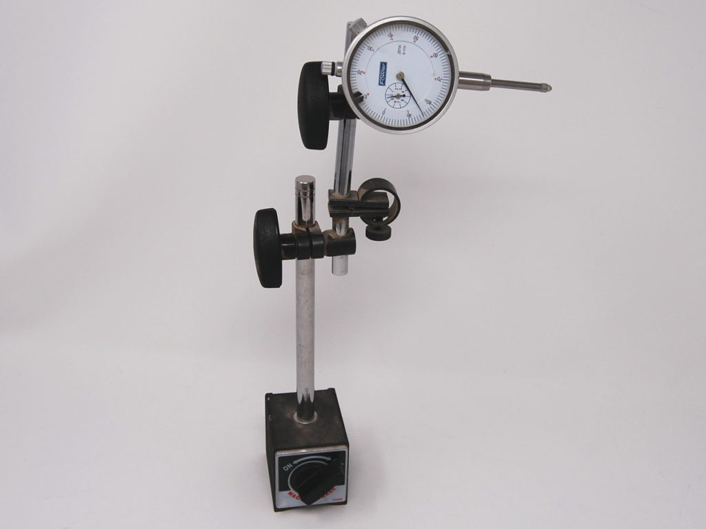
Dial Indicator
To check for alignment, you will need a dial indicator, which is a precision measurement tool used for measuring small distances and angles. It is useful for setting up and checking shop machinery and equipment. Models are available with magnetic bases that will easily attach to machinery tables.
To check for alignment, perform the following steps.
- Lock out the saw, install the largest blade the saw will take, and raise it to full height above the table.
- Put the mitre gauge in the slot it is most used in. Make sure the miter gauge has no play in the slot.
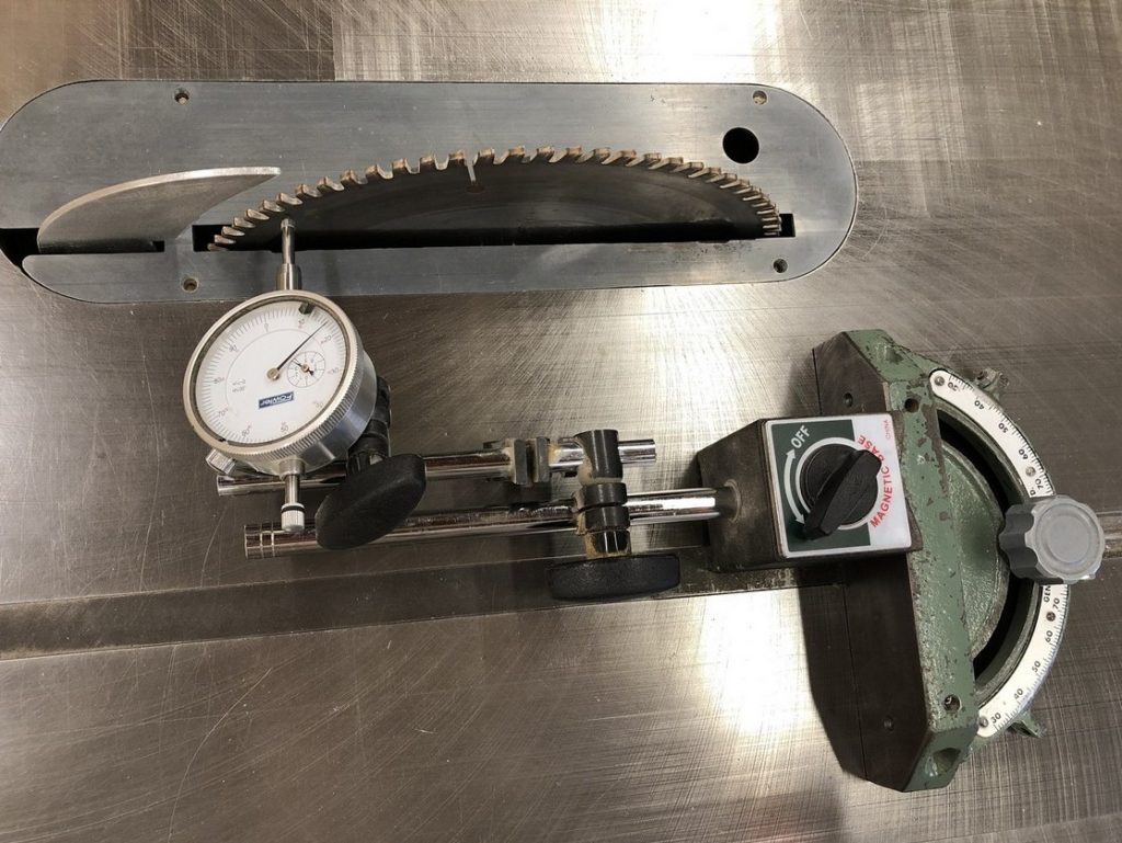
- Install the indicator in approximate position as follows. If your dial indicator has a magnetic base, attach it to the mitre gauge. You may need to remove the wooden auxiliary fence. If your dial indicator is not magnetic, attach it to a block of wood, and clamp the block to the miter gauge. In both cases, the tip of the indicator should be close to and pointed toward the blade.
- Slide the dial indicator so it makes contact with the plate of the saw blade, close to but not touching the teeth. The farther the measurement is made from the centre of the blade, the more accurate it will be. The indicator should be engaged so it makes a few turns of the dial.
- Starting closest to you at the front of the blade, mark the location on the saw blade where the tip of the dial indicator touches.
- Zero the dial indicator.
- Slide the mitre gauge with the attached dial indicator to the back of the saw blade.
- Rotate the saw blade until the mark you made is at the point of the dial indicator.
- Note the measurement.
- If the indicator stays on zero, the mitre slots are in alignment with the blade. If the indicator moved, the slots are out by the amount of the second measurement.
To make the necessary adjustments, follow the steps below.
- On a cabinet saw, find and just-loosen the bolts that fasten the table top to the cabinet. It is easiest to loosen 3 bolts and use the last as a pivot point.
- Use a mallet to tap the table in the direction it needs to move to bring it into alignment.
- Use the dial indicator to re-measure for alignment. You will need to zero the dial indicator.
- Keep adjusting the table, remembering to zero out the dial indicator each time.
- When the slots are aligned, tighten the table bolts.
- With the bolts tight, check the alignment one final time to ensure tightening the bolts did not affect the alignment.
Adjusting the rip fence (T-style) to the blade
The procedure for checking alignment of the rip fence to the blade is similar to checking the mitre slots for parallel.
- Lock out the saw, install the largest blade the saw will take, and raise it to full height above the table.
- Position a dial indicator against the rip fence. The tip of the indicator should be close to and pointed toward the blade.
- Position the rip fence so that the dial indicator makes contact with the plate of the saw blade, close to but not touching the teeth. The farther the measurement is made from the centre of the blade, the more accurate it will be. The indicator should be engaged so it makes a few turns of the dial.
- Starting closest to you at the front of the blade, mark the location on the saw blade where the tip of the dial indicator touches.
- Zero the dial indicator.
- Slide the dial indicator to the back of the saw blade.
- Rotate the saw blade until the mark you made is at the point of the dial indicator.
- Note the measurement.
- If the indicator stays on zero, the fence is in alignment with the blade. If the indicator moved, the fence is out by the amount of the second measurement.
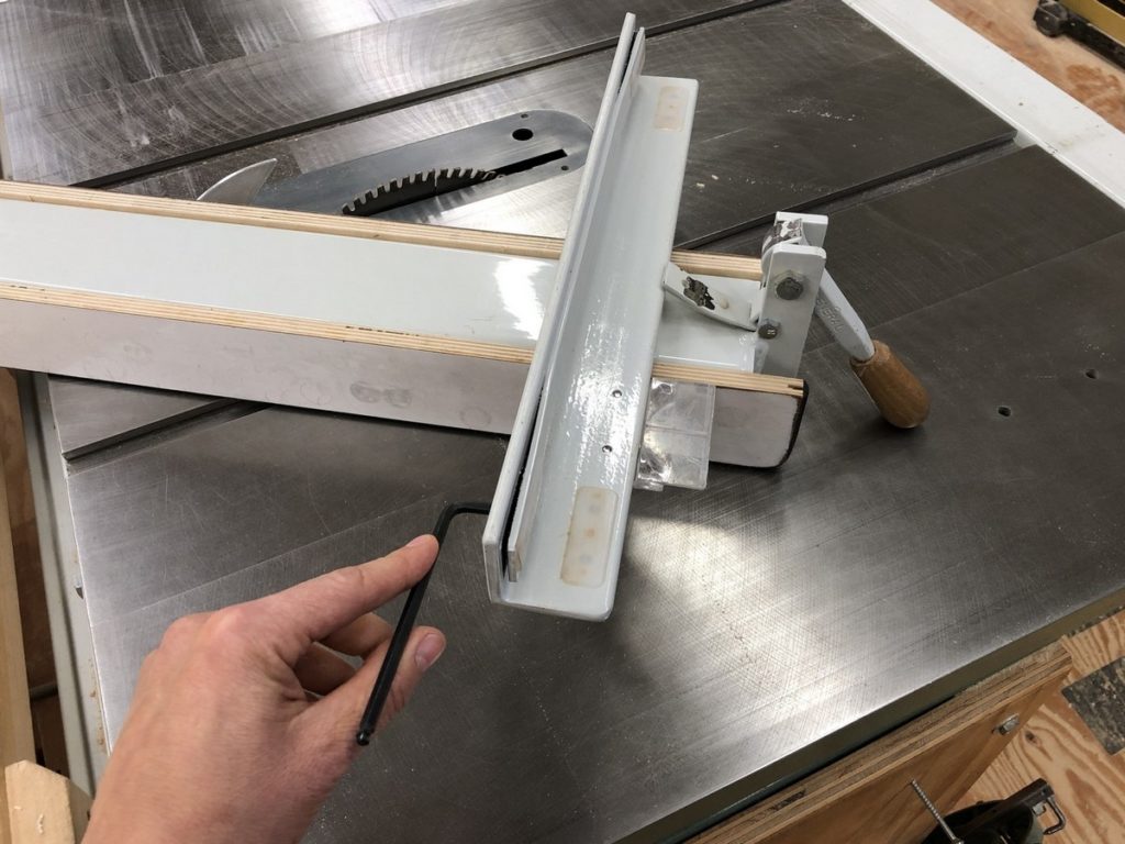
To make the necessary adjustments in a ‘T’ style fence, follow the steps below.
- With the fence on the saw, note which way it needs to pivot to bring it into alignment.
- Unlock the fence and flip it over on the saw table.
- Using a hex wrench, adjust the set screws to move the fence in the direction it needs to move.
- Install the fence on the saw, and check for parallel with the dial indicator.
- Keep adjusting and checking the fence until it is parallel to the blade.
Setting and adjusting the positive 90° and 45° stops
Every table saw has stops that limit the travel of the trunnion assembly at 90° and 45°. Having these accurately set saves time with set-up and improves accuracy. Occasionally, they may need to be adjusted. If the saw is not reliably returning to 90° and 45°, first check that there is no debris or sawdust built up on the stops or on the trunnion assembly.
To make the necessary adjustments, follow the steps below.
- Lock out the saw, install the largest blade the saw will take, and raise it to full height above the table.
- Using an engineer’s square or a reliable 45° measuring tool such as a drafting set square, set the blade to the appropriate angle.
- Ensure the square is touching the plate of the saw blade, not the carbide teeth. Use the tilt handwheel to bring the blade into perfect alignment with the square.
- Locate the lock nut for the positive stop. Refer to the tool’s manual if required.
- Loosen the nut and adjust it until it contacts the trunnion assembly in the correct location. Depending on which way the stop needs to move, it may be necessary to use the tilt handwheel and swing the assembly out of the way to provide clearance.
- Tighten the nut, then tilt the saw a few degrees before returning it to position against the stop.
- Check the angle to confirm the stop location, you may have to try a few times to get a reliable reading.
- Make a test cut in a piece of wood, this is the most reliable way to check the setting.
Electrical and drive belts
Periodically inspect the power cord and electrical wiring for damage or fraying. Check the plug for loose connections. A qualified electrician should repair electrical issues on any machinery.
With use, the drive belts on any machine will wear out. A worn or damaged belt causes undesirable vibration. Look for hardness, cracking, and fraying; replace the belts as needed. Most table saws use a pair of belts, these should be replaced at the same time. Proper tension on the belts is important, too-tight belts puts unnecessary strain on the pulley and arbor bearings. A too-loose belt will result in slippage and the saw losing power, possibly stalling in the cut.
To check the belt tension, push on the belt at the midpoint between the pulleys, it should flex slightly. With the saw locked out, it should be possible to turn the saw blade easily by hand.
