Module 23: Arraying
Learning Outcomes
When you have completed this module, you will be able to:
- Describe how drawing objects are arrayed in both polar and rectangular patterns.
- Apply the ARRAYCLASSIC command to array objects in polar or rectangular patterns.
- Describe and apply five additional the methods of selecting objects; window polygon, cross polygon, fence, lasso window, and lasso cross window.
- Describe how to find the center of and insert a circle inside a regular polygon.
Arraying
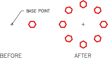
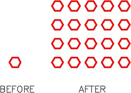
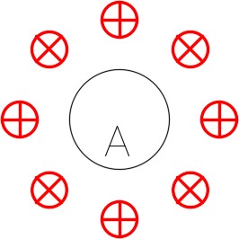
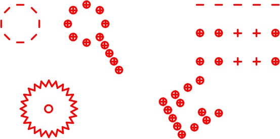
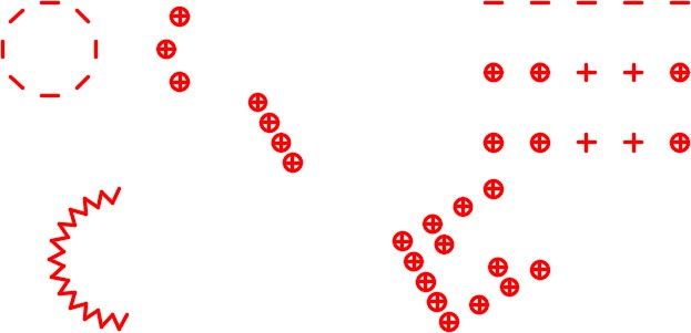
The ARRAY command is used to create multiple copies of objects in a polar or rectangular pattern. See Figure 23-1 and 23-2. It is another one of those powerful commands that, when used at the right times, can prove to be very productive.
AutoCAD Command: ARRAYCLASSIC
The ARRAYCLASSIC command displays a dialogue box that is used to create multiple copies of objects either in a rectangular or a polar pattern.
Shortcut: none
WORKALONG: Using the ARRAY Command – Part 1
Step 1
Start a new drawing using the template: 2D Layout English.
Step 2
Save and name the drawing: AutoCAD 2D Workalong 23-1.
Step 3
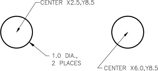
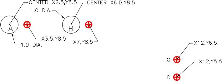
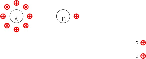
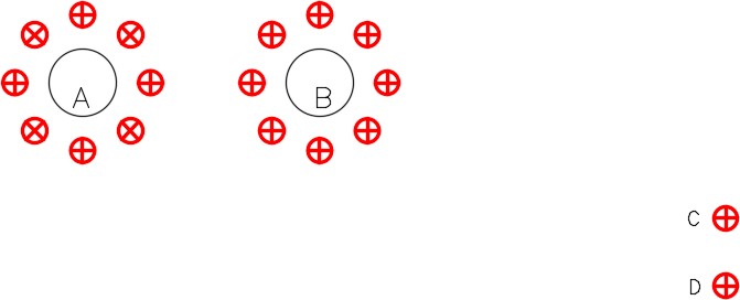
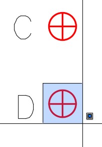
On layer: Construction, draw the two circles shown in the figure. (Figure Sep 3)
Step 4
On layer: Text, using the text style: 2D Modules, insert the text A and B. Select the location of the text by eye and use a text height to match the figure as close as possible. (Figure Step 4)

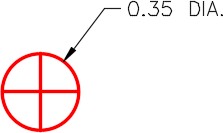
Step 5
On layer: Object, draw a 0.35 diameter circle and two lines snapping them from quad to quad as shown in the figure. Draw it anywhere on the drawing. (Figure Step 5)
Step 6
Using the COPY command, copy the circle you drew in Step 5, four times, to the absolute coordinates shown in the figure. Add the text C and D using the same specifications as the text in Step 4. (Figure Step 6)
Step 7
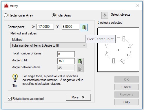
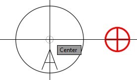
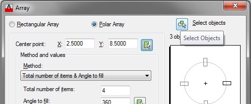
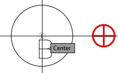
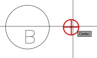
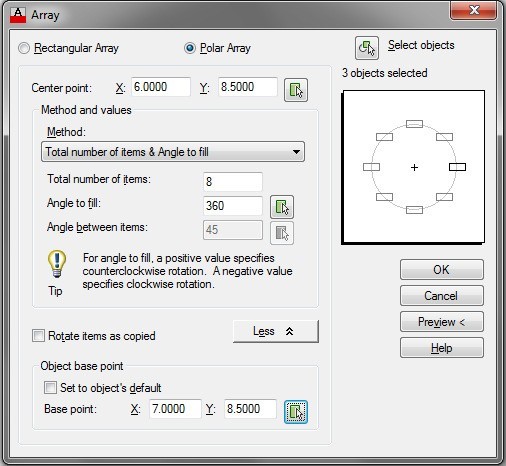
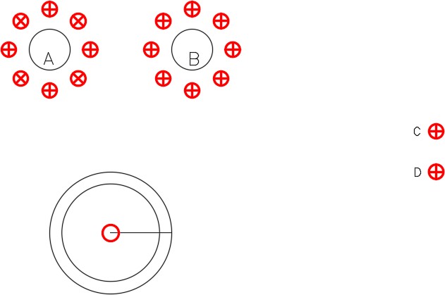
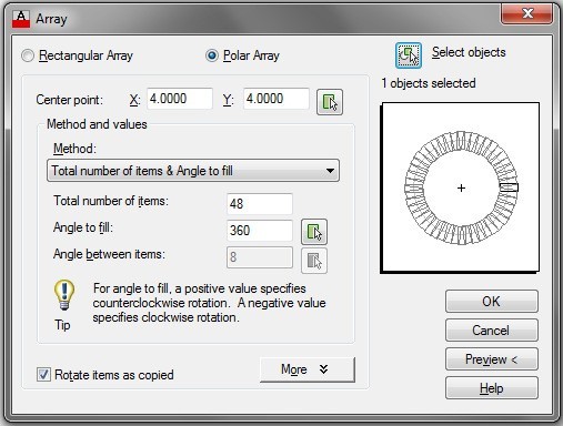
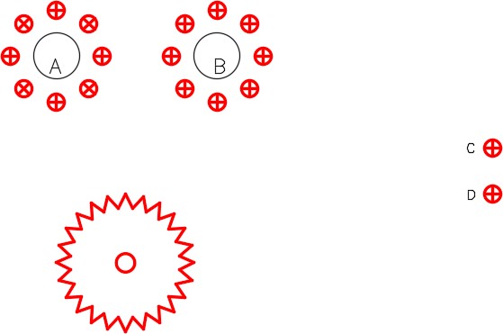
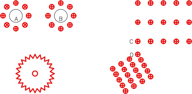
Enter the ARRAYCLASSIC command to open the Array dialogue box. In the Array dialogue box, enable Polar Array . Click the Pick Center Point show me icon. When you are prompted for the center point of the array, snap to the center of circle A. (Figure Step 7A and 7B)
Step 8
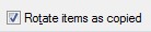
Enable Rotate items as copied. (Figure Step 8)
Step 9
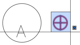
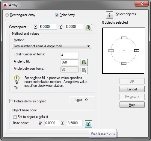
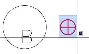
Click the Select objects icon. When you are prompted to Select objects, use a window to select the small circle as shown in the figure. (Figure Step 9A and 9B)
Step 10
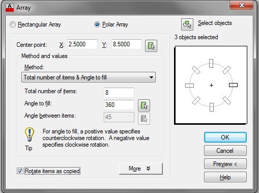
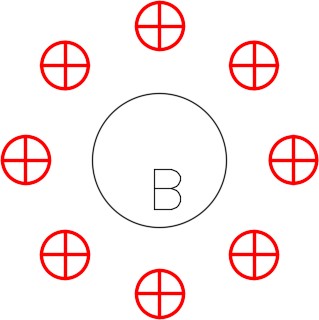
Set the Total number of items to 8 and Angle to fill: to 360.00. The Array dialogue box should match the figure. Click OK and your array should appear as shown in Figure Step 10B. (Figure Step 10A. 10B, and 10C)
Step 11
Enter the ARRAYCLASSIC command. Using what you learn in Step 7, enable Polar Array and click the Pick Center Point icon. When you are prompted for the center point of the array, snap to the center of circle B. (Figure Step 11)
Step 12
Disable Rotate items as copied. Click the More button, to the right of the Rotate items as copied button, to expand it. Click the Pick Base Point icon. When you are prompted to select the base point, snap to the center of small circle. (Figure Step 12A and 12B)
Step 13
Click the Select objects button. When you are prompted to Select objects, use a window to select the small circle as shown in the figure. Set the Total number of items to 8 and Angle to fill: to 360.00. (Figure Step 13A, 13B, 13C, and 13D)
Step 14
Save and close the drawing.
WORKALONG: Using the ARRAY Command – Part 2
Step 1
Open the drawing: AutoCAD 2D Workalong 23-1. (Figure Step 1)

Step 2
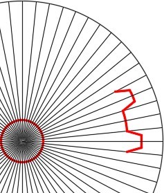
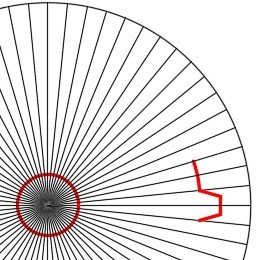
Using the figures as a reference, draw the two circles and the line on layer: Construction. On layer: Object, draw the small inner circle. (Figure Step 2A, 2B, and 2C)
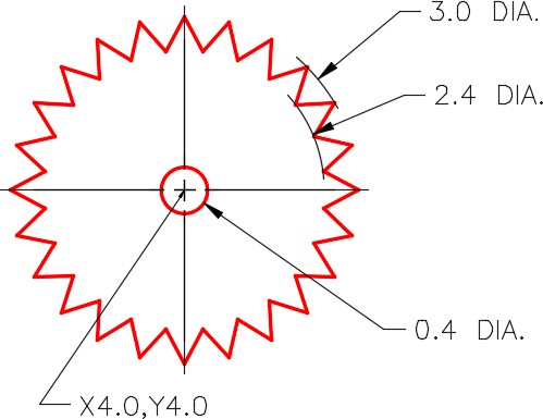
Step 3
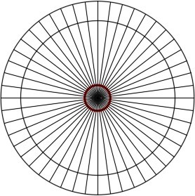
Enter the ARRAYCLASSIC command to open the Array dialogue box. Using what was taught earlier in this module, array the line 48 times. Rotate the line as it is arrayed. (Figure Step 3A and 3B)
Step 4
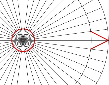
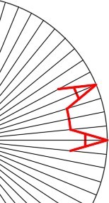
On layer: Object, draw one tooth by snapping to the intersection of the lines and circles as shown on the figure. (Figure Step 4)
Step 5
Array the tooth 24 times. (Figure Step 5)
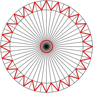
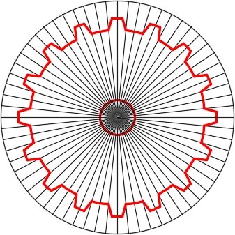
Step 6
Freeze layer: Construction. The completed drawing should match the figure. (Figure Step 6)

Step 7
Save and close the drawing.
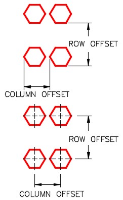
USER TIP: In a rectangular array, the offset distance is measured from a point on the object to the same point on the arrayed object.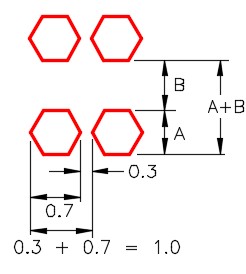
When arraying an object where only the distance between the objects is known, add the width of the object to the spacing for the column offset and height of the object to the spacing for the row offset.
If the distances from center to center of the object are known, simply use them as the offset distances.
WORKALONG: Using the ARRAY Command – Part 3
Step 1
Open the drawing: AutoCAD 2D Workalong 23-1. (Figure Step 1)
Step 2
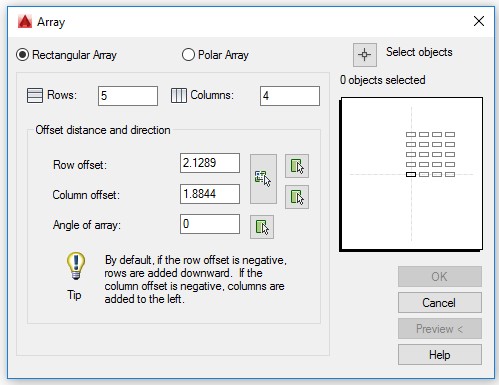
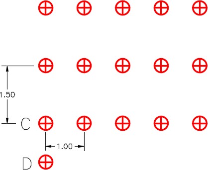
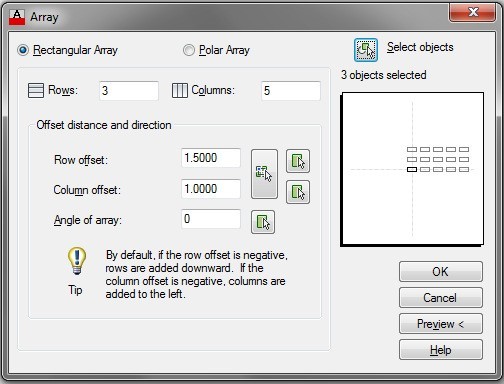
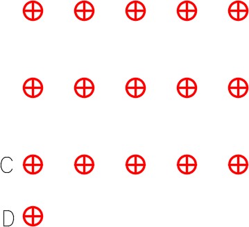
Enter the ARRAYCLASSIC command. In the Array dialogue box, enable Rectangular Array. Set the number of rows to 3 and number of columns to 5. Set the Row offset to 1.5 and Column offset to 1.0. Click the Select object icon and when prompted to Select objects, use a window to select circle C plus the lines. (Figure Step 2A, 2B, and 2C)
Step 3
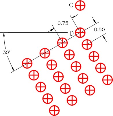
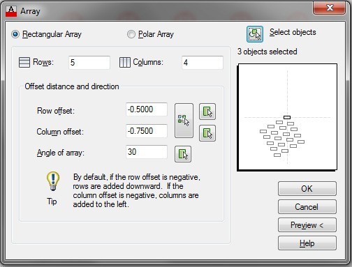
Enter the ARRAYCLASSIC command. In the Array dialogue box, enable Rectangular Array. Set the number of rows to 5 and number of columns to 4. Set the Row offset to – 0.5 and Column offset to -0.75. Set the Angle of array to 30. Click the Select object icon and when you are prompted to Select objects, use a window to select circle D and the two lines. (Figure Step 3A, 3B, 3C, and 3D)
Step 4
Save and close the drawing.
WORKALONG: Using Polygon Windows and Fences to Select Objects
Step 1
Open the drawing: AutoCAD 2D Workalong 23-1.
Step 2
Using the SAVEAS command, save and name the drawing: AutoCAD 2D Workalong 23-2.
Step 3
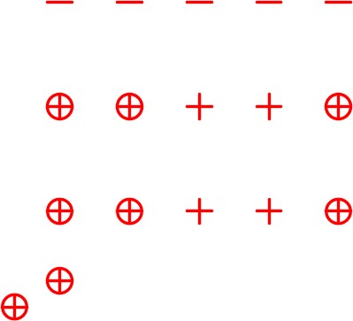
Turn layers: Construction and Text off. (Figure Step 3)

Step 4
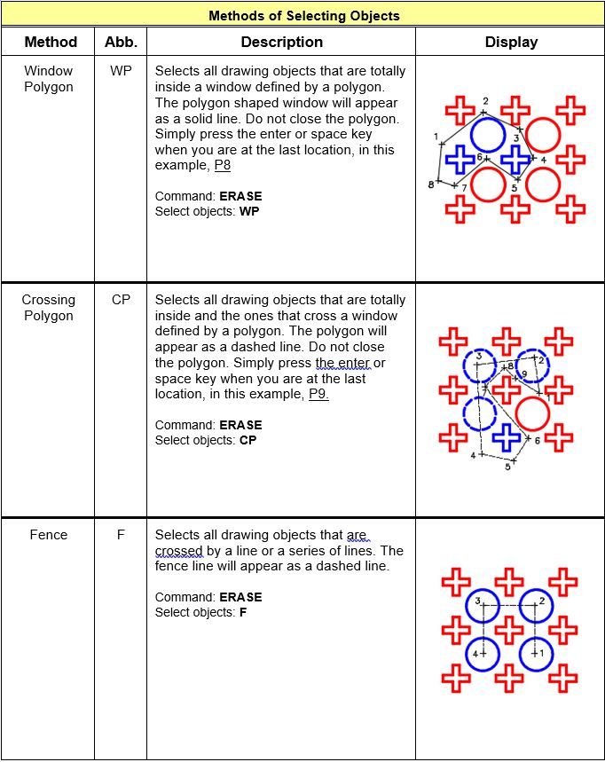
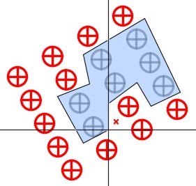
Enter the ERASE command as shown below. Use a window polygon to select the objects. (Figure Step 4A and 4B)
Command: ERASE Select objects: WP
First polygon point:
Specify endpoint of line or [Undo]:
Specify endpoint of line or [Undo]:
Specify endpoint of line or [Undo]:
Specify endpoint of line or [Undo]:
Specify endpoint of line or [Undo]:
Select objects:
Command:
Step 5
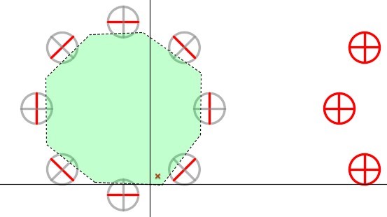
Enter the ERASE command as shown below. Use a cross polygon window to select the objects to be erased. (Figure Step 5A and 5B)
Command: ERASE Select objects: CP
First polygon point:
Specify endpoint of line or [Undo]:
Specify endpoint of line or [Undo]:
Specify endpoint of line or [Undo]:
Specify endpoint of line or [Undo]:
Specify endpoint of line or [Undo]:
Specify endpoint of line or [Undo]:
Specify endpoint of line or [Undo]:
Select objects:
Command:
Step 6
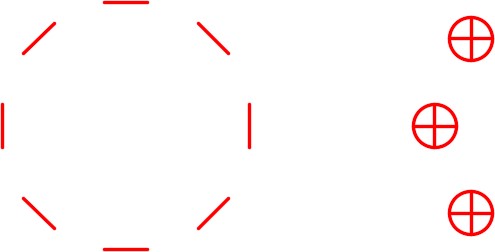
Enter the ERASE command as shown below. Use a fence to select the objects to be erased. (Figure Step 6A and 6B)
Command: ERASE Select objects: F
First polygon point:
Specify endpoint of line or [Undo]:
Specify endpoint of line or [Undo]:
Specify endpoint of line or [Undo]:
Specify endpoint of line or [Undo]:
Specify endpoint of line or [Undo]:
Specify endpoint of line or [Undo]:
Specify endpoint of line or[Undo]:
Select objects:
Command:
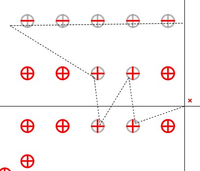
Step 7
Using what you learned, use the COPY command and a cross polygon window to select the objects, copy the 4 circles and their lines as shown in the figure.
(Figure Step 7A, 7B, and 7C)
Step 8
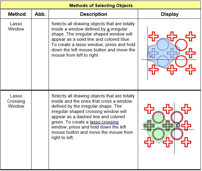
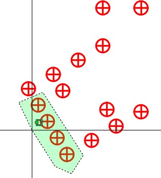
Use the lasso windows method to erase 5 circles. Without entering a command, press the left mouse button and while holding it down, move the mouse from left to right. The irregular shape should be colored blue. All objects totally inside the window will be selected. With the object selected, press the Delete key. (Figure Step 8A, 8B, and 8C)
Step 9
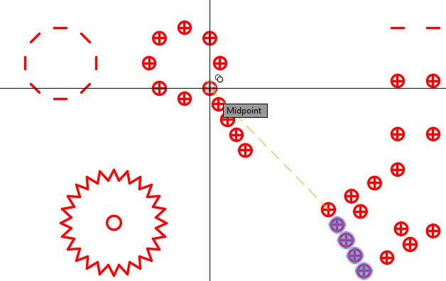
Use the lasso crossing windows method. Without entering a command, press the left mouse button and while holding it down, move the mouse from right to left. The irregular shape should be colored green. All objects totally inside and ones that cross the window will be selected. With the object selected, press the Delete key. (Figure Step 9A, 9B, and 9C)
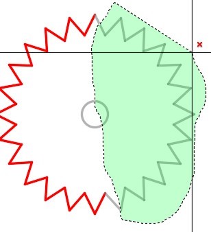

Step 10
save and close the drawing.
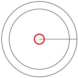
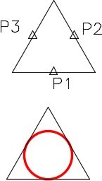
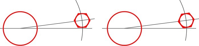
Geometry Lesson: Finding Centers and Placing Circles inside Regular Polygons
Method 1
Insert a circle that is tangent to the midpoint of three sides of the regular polygon. The center of the circle is the center of the polygon. See Figure 23-4.
Insert a circle using the 3P option in the CIRCLE command. For the three points, snap to the midpoints of any three lines.
Command: CIRCLE
Specify center point for circle or [3P/2P/Ttr (tan tan radius)]: 3P
Specify first point on circle: (mid) P1
Specify second point on circle: (mid) P2
Specify third point on circle: (mid) P3
Command:
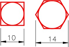
Method 2
Insert the circle using the 3P option in the CIRCLE command and snap to the tangent point of any three of sides of the regular polygon. See Figure 23-5.
Command: CIRCLE
Specify center point for circle or [3P/2P/Ttr (tan tan radius)]: 3P
Specify first point on circle: (tan) P4
Specify second point on circle: (tan) P5
Specify third point on circle: (tan) P6
Command:

Key Principles
Key Principles in Module 23
- When an object is arrayed, all objects created in the array will retain the properties of the original objects, even the layer they reside on. This happens regardless of the current layer when the ARRAYCLASSIC command is executed.
- In a rectangular array, the offset distance is measured from the one point on the object to the same point on the arrayed object.
- A Window Polygon selects all drawing objects that are totally inside a window defined by a polygon. The polygon shaped window will appear as a solid line. A Cross Polygon selects all drawing objects that are totally inside and the ones that cross a window defined by a polygon. The polygon will appear as a dashed line. A Fence selects all drawing objects that are crossed by a line or a series of lines.
Lab Exercise 23-1
Time allowed: 60 minutes.
| Drawing Name | Template | Units |
|---|---|---|
| AutoCAD 2D Lab 23-1 | 2D Layout Metric | Millimeters |
Step 1
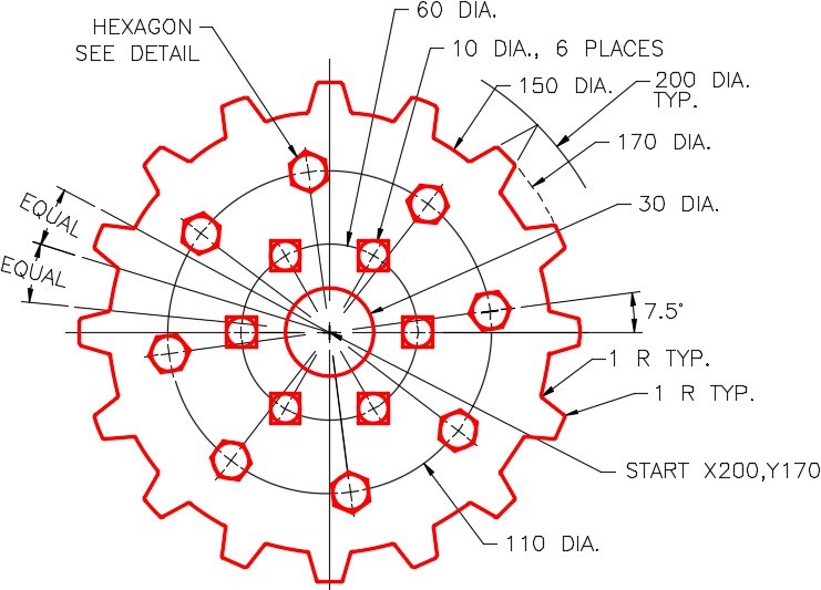
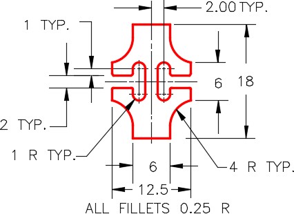
On layer: Object, draw the object shown in the figures. (figure Step 1A, 1B and 1C).
Step 2
Set the insertion units and insert the key. Check the drawing for accuracy.
Detail
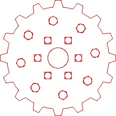
Completed Drawing
Hint 1
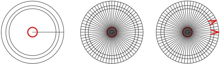
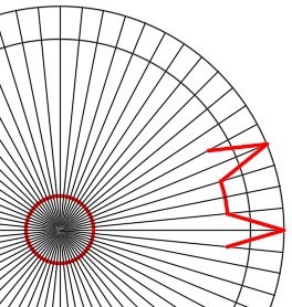
Draw and then array the line 64 times and draw two teeth (Figure Hint 1)
Hint 2
Trim the circles and lines as shown in the figure. (Figure Hint 2A, 2B and 2C)
Hint 3
Delete the unnecessary lines and arcs. (Figure Hint 3)
Hint 4
Array the objects 16 times. (Figure Hint 4)
Hint 5
Draw the hexagon first with the top and bottom lines horizontal. Locate its center using the dimensioned drawing. After it is drawn, rotate it using a Reference to the correct angle. (Figure Hint 5)
Lab Exercise 23-2
Time allowed: 60 minutes.
| Drawing Name | Template | Units |
|---|---|---|
| AutoCAD 2D Lab 23-2 | 2D Layout Metric | Millimeters |
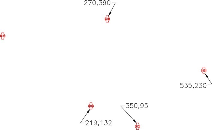
Step 1
On layer: Object, draw the object shown in the figure. Draw it anywhere on the drawing. (Figure Step 1)
Step 2
Copy the object to each location as shown in the figure. (Figure Step 2)
Step 3
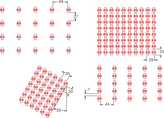
Array the object as shown below. (Figure Step 3)
Step 4
Save and close the drawing.
Hint 1
Draw one arc as shown. The four step are shown in the figure. If you need help understanding you can see the Geometry Lesson in Module 20. (Figure Hint 1)
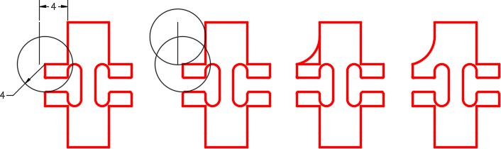
Figure Hint 1
Hint 2
After one arc is drawn, mirror it to the right side. Then mirror the two top arc to the bottom. Trim and erase the lines to complete. (Figure Hint 2)
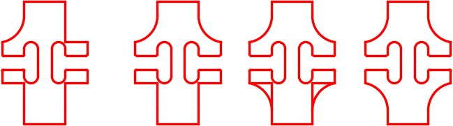
Figure Hint 2
