Module 32: Hatching
Learning Outcomes
When you have completed this module, you will be able to:
- Describe crosshatching, hatching boundaries, hatching patterns, and associative and nonassociative hatching.
- Explain sectional views, sections, and hatching in sectional views.
- Apply the HATCH and HATCHEDIT commands to insert and edit crosshatching patterns.
Crosshatching
Many drawings require areas to be filled with a pattern. This is called crosshatching or just hatching. There are many uses for hatch patterns on a drawing including displaying an object’s material type, the solid material that was cut through in the sectional view, difference materials used in one area to another, plus many other applications.
Hatching Boundaries
The HATCH command is used to insert hatch patterns. It allows you to select two different methods of selecting the boundary of the area to be filled in with the hatch pattern. The first method is picking an internal point and allow the HATCH command to find an enclosed boundary and the second method involves using an existing closed polyline to define the hatching boundary. The first method works well most of the time but for more complicated drawings, the second method must be used.
Hatching Patterns
There are many predefined hatch patterns including ANSI standards, ISO standards, and a solid fill pattern that are part of AutoCAD’s software. All hatch patterns are constructed using lines but hatch patterns are inserted as a single drawing object. This helps them to be easily manipulated and also keeps the drawing’s database small. A hatching pattern can be exploded, using the EXPLODE command, to convert it to individual lines.
Associative Verses Nonassociative Hatching
An associative hatch will automatically adjust when the boundary, that was used to create it, is moved or changed. A nonassociative hatch remains the same size and in the same location regardless of the changes made to the hatch’s boundary. An associative hatch is the default in the HATCH command.
An associative hatch can be changed to a nonassociative hatch by changing the properties of the object with the Properties window or with the HATCHEDIT command. A nonassociative hatch can never be changed to a associative hatch. It would have to be deleted and reinserted.
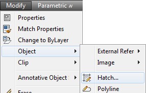
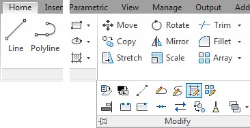
AutoCAD Command: HATCH
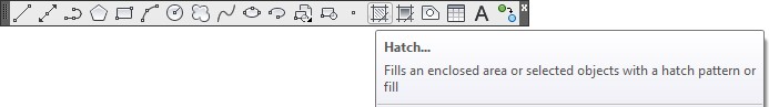
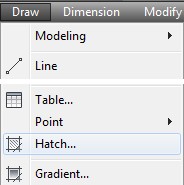
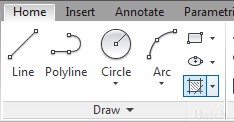
The HATCH command is used to insert a hatch pattern.
Shortcut: H
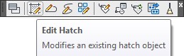
AutoCAD Command: HATCHEDIT
The HATCHEDIT command is used to edit an existing hatch pattern.
Shortcut: none
Drafting Lesson: Cross Sections – Part 1
When a view of an object requires a clearer description of its interior or it is hard to dimension because of the hidden lines, a cross section view can be drawn in place of the normal multiview. See Figure 32-1
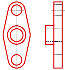
Normal Front and Right Side View of an Object
A cross section view, also called a section, is a view of the object as if it were cut along a cutting plane and the two pieces pulled apart exposing the inside of the object. See Figure 32-2 and 32-4.
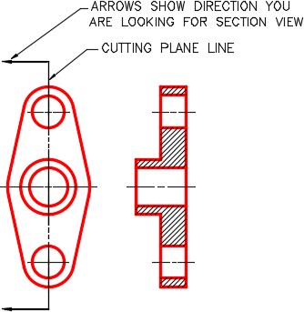
A Front view and Right Side Section View
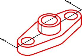
3D Model of the Object Showing the Cutting Plane Line
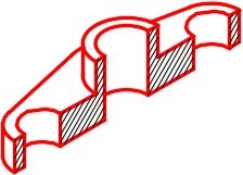
3D Model of the Object Showing it Cut on the Cutting Plane Line
A cutting plane line is the line along the object where the cut would have been made. See Figure 32-2 and 32-3. The arrows point in the direction that you are looking when drawing the section view. The surfaces of the object that are solid, when cut, are crosshatched.
WORKALONG: Inserting Hatch Patterns
Step 1
Start a new drawing using the template: 2D Layout English.
Step 2
Save and name the drawing: AutoCAD 2D Workalong 32-1.
Step 3
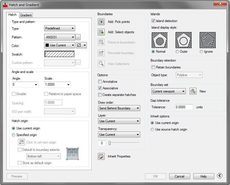
Enter the HATCH command. It will open the Hatch and Gradient dialogue box. The More/Less icon, in the bottom right corner of the dialogue box, is used to open or close the advanced portion of the dialogue box. (Figure Step 3)
Step 4
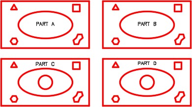
Open drawing: AutoCAD 2D Workalong 30-1. Using the SAVEAS command, save and name the drawing: AutoCAD 2D Workalong 32-1. (Figure Step 4)
Step 5
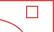
Using the ROTATE command, rotate the diamond 45 degrees, using its center as the base point, to change it to a square. (Figure Step 5)
Step 6
Using the COPY command, copy the bottom object three times locating them by eye. Align the copies and center them using what you have learned to this point in the book. Their exact location is not important for this exercise but ensure that they are aligned.
Step 7
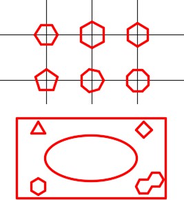
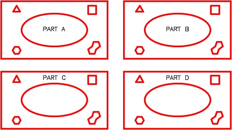
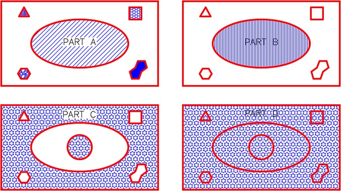
Erase the 6 regular polygons above the rectangles. On layer: Text, using the DTEXT command, add the text in each copy. Use the text style: 2D Modules at a height of 0.25. Your drawing should appear similar to the figure. (Figure Step 7)
Step 8
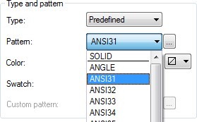
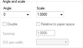
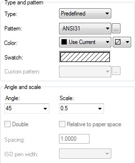
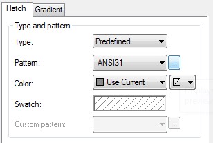
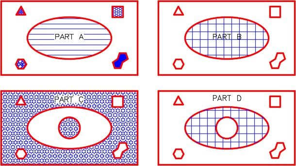
Set the current layer to layer: Hatch. Enter the HATCH command. In the Hatch and Gradient dialogue box, set the Type and pattern to ANSI31. In the Angle and scale box, set the Angle to 0 and the Scale to 1. (Figure Step 8A and 8B)
Step 9
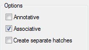
In the Options box, ensure that Associative is enabled. (Figure Step 9)
Step 10
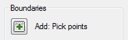
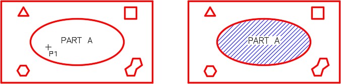
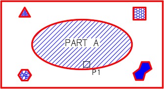
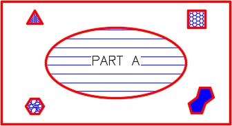
In the Boundaries box, click the Add Pick points icon and then pick the point P1 in Part A as shown in the figure. The hatch pattern will hatch the ellipse, without hatching over the text. (Figure Step 10A, 10B, and 10C)
Step 11
Click OK to complete the command.
Step 12
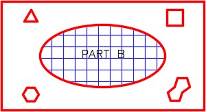
Enter the HATCH command again. In the Hatch dialogue box, set the Pattern to ANSI31, the Angle to 45 degrees and the Scale to 0.5. (Figure step 12)
Step 13
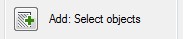
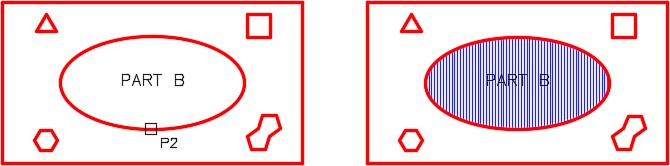
Click the Add Select objects icon and when prompted, select the ellipse in Part B as shown in the figure. The hatch pattern will ignore everything inside the object as you can see in the figure. (Figure Step 13A, 13B, and 13C)
Step 14
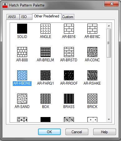
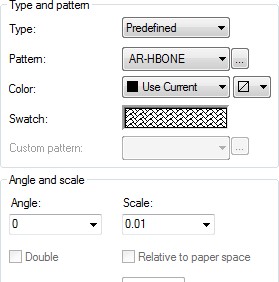
Enter the HATCH command. Click the … icon at the end of the Pattern box. This will open the Hatch Pattern Palette dialogue box. Select the AR-HBONE pattern. (Figure Step 14A and 14B)
Step 15
With the AR-HBONE pattern selected, set the Angle to 0 and the Scale to 0.01. (Figure Step 15)
Step 16
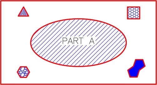
Using what you just learned, insert the hatching patterns in Part A using the Select Object method. Use the following specifications: (Figure Step 16)
Triangle – Pattern Hr-HBone
Angle – 0 Scale – 0.1
Square – Pattern Honey
Angle – 0 Scale – 0.5
Hexagon – Pattern Gravel
Angle – 0 Scale – 0.25
8 Sided Polygon – Pattern Solid, Angle N/A – Scale – N/A
Step 17
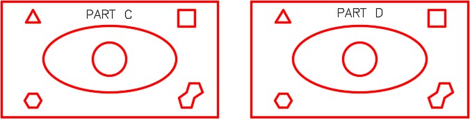
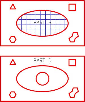
On layer: Object, draw a 1 inch diameter circle in the center of the ellipses in Part C and Part D. (Figure Step 17)
Step 18
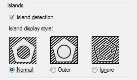
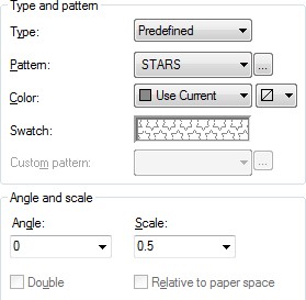
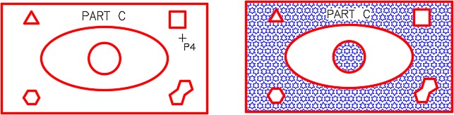
Enter the HATCH command. Ensure that the Islands box is set to Normal as shown in the figure. Set the Types and pattern to Stars, the Angle to 0 and Scale to 0.5. (Figure Step 18A and 18B)
Step 19
Click the Add Pick points icon. In Part C, select inside the rectangle as shown by P4. Part C should hatch as shown in the figure. (Figure Step 19A and 19B)
Step 20
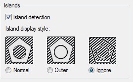
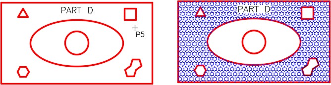
Enter the HATCH command and set the Islands display style to Ignore. (Figure Step 20)
Step 21
Click the Add Pick points icon and select the location P5 in Part D. (Figure Step 21A and 21B)
Step 22
Your completed drawing should match the figure. (Figure Step 22)
Step 23
Save and close the drawing.
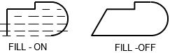
MUST KNOW: The FILL command controls the fill of a hatching pattern plus other feature in AutoCAD. If toggled off, hatch patterns will not appear on the drawing. This can help you work faster since the drawing regenerates faster. Do not forget to turn the FILL on when finished. The REGEN command must be executed to display the current fillmode after the FILL command has been executed.
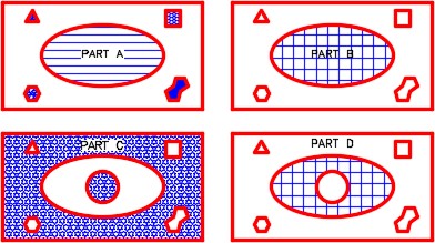
WORKALONG: Using the HATCHEDIT Command
Step 1
Open the drawing: AutoCAD 2D Workalong 32-1. Using the SAVEAS command, save and name the drawing: AutoCAD 2D Workalong 32-2. (Figure Step 1)

Step 2
Enter the HATCHEDIT command, as shown below. (Figure Step 2)
Command: HATCHEDIT
Select hatch object: P1
(Select the hatching pattern inside the ellipse of PART A. This will open the Hatch Edit dialogue box.)
Step 3
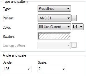
In the Angle and scale box change the Angle to 135 and the Scale to 2 as shown in Figure Step 3A. Click OK. Notice the change to the hatching pattern. (Figure Step 3A and 3B)
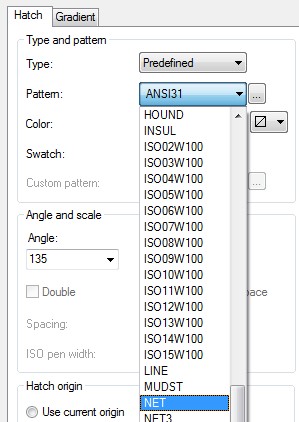
Step 4
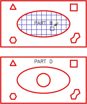
To edit the hatching pattern for Part B, double click the pattern to open the Hatchedit dialogue box. On the pull-down list for Pattern, select Net. (Figure Step 4A and 4B)
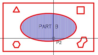
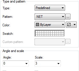
Step 5
In the Angle and scale box, change the Angle to 0 and the Scale to 3. Click OK. Note the change to the hatching pattern. (Figure Step 5A and 5B)
Step 6
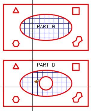
Delete the hatch in Part D. (Figure Step 6)
Step 7
Enter the HATCH command and click the Inherit Properties icon. Select the Net hatch pattern in Part B. With the paint brush graphic cursor, select inside the ellipse in Part D. (Figure Step 7A, 7B, 7C, and 7D)

Step 8
Enter the commands shown below. Note how the hatching patterns will not display when Fill is Off and display when it is On. (Figure Step 8A and 8B)
Command: FILL
Enter mode [ON/OFF] <ON>: OFF
Command: REGEN
Regenerating model.
Command: FILL
Enter mode [ON/OFF] <OFF>: ON
Command: REGEN
Regenerating model. Command
Key Principles
Key Principles in Module 32
- When using the Select object method to hatch, a closed polyline must be created before executing the HATCH command. Since a circle, rectangle, or an ellipse are closed objects, they can be used as a closed polyline.
- All hatch patterns are constructed using lines but the hatch pattern is created as a single object in the drawing. This helps to manipulate the hatch patterns and keep the drawing’s database smaller. A hatching pattern can be exploded back into its individual line objects using the EXPLODE command.
- An associative hatch will automatically adjust when the boundary, that was used when it was created, is moved or changed. A nonassociative hatch remains the same size and in the same location regardless of the changes made to the hatch boundary.
Lab Exercise 32-1
Time allowed: 40 minutes.
| Drawing Name | Template | Units |
|---|---|---|
| AutoCAD 2D Lab 32-1 | 2D Layout English | Inches |
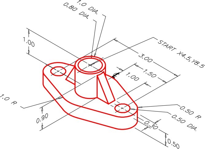
Step 1
On layer: Object, draw the top and front views of the object shown in figures. (Figure Step 1)
Step 2
Use the spacing between views as shown in the figure. (Figure Step 2)
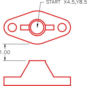
Top and Front View Locations
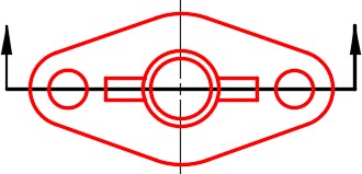
Step 3
On the Front view, add the full cross section. The cutting plane line is shown in Figure Step 3A. On layer: Hatch, insert the cross hatching pattern using the pattern ANSI31. Select an appropriate scale. (Figure Step 3A and 3B)
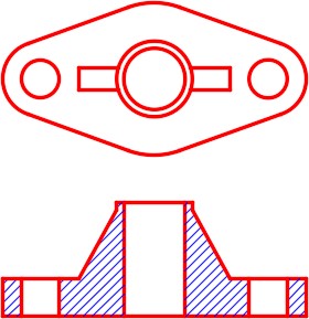
Completed Drawing
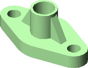
Hint 1
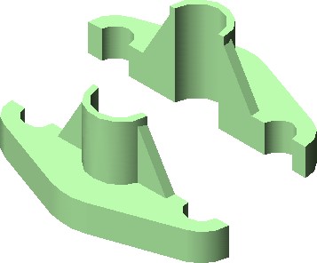
If you have trouble visualizing the object and the section view you have to draw, study the solid models of the object shown below. The solid modeling views were done using AutoCAD. Solid Modeling is taught in the AutoCAD 3D book.
Lab Exercise 32-2
Time allowed: 50 minutes.
| Drawing Name | Template | Units |
|---|---|---|
| AutoCAD 2D Lab 32-2 | 2D Layout English | Inches |
Step 1
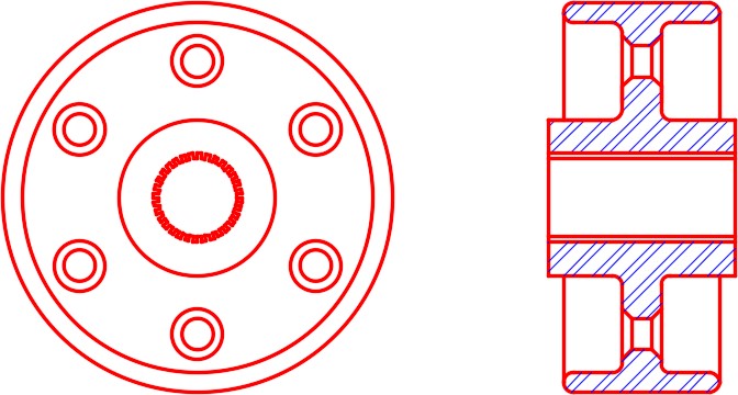
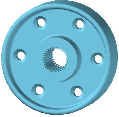
On layer: Object, draw the Front and Right Side views of the figure. Draw the Right Side view as a full section. (Figure Step 1A, 1B, and 1C)
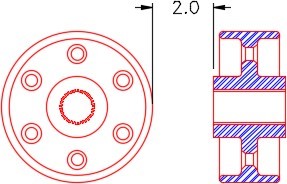
Location of the Views
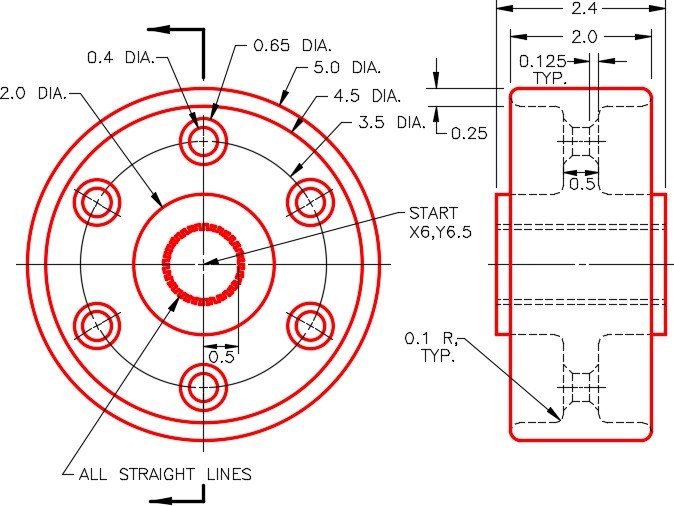
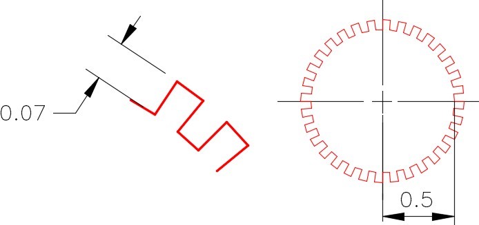
Detail of Gear Teeth
Step 2
On layer: Hatch, insert the cross hatching pattern using the pattern ANSI32 at a scale of 0.5. (Figure Step 2)
Hint 1
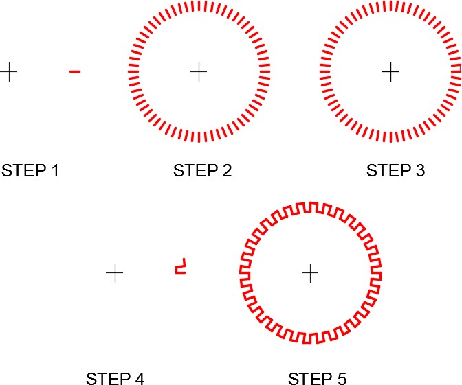
To draw the gear teeth, see the five steps in the figure. Step 1 – Draw one line of the teeth. Step 2 – Array the line 64 times. Step 3 and 4 – Add lines to create one tooth and the repeat pattern. Erase the unwanted lines. Step 5 – Array the tooth 32 times. (Figure Hint 1)
Hint 2
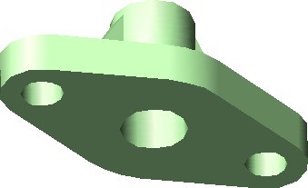
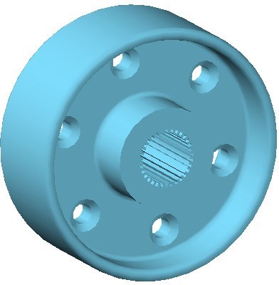
If you have trouble visualizing the object, study the solid models of the object shown below. The solid modeling views were done using AutoCAD. Solid Modeling is taught in the AutoCAD 3D book.
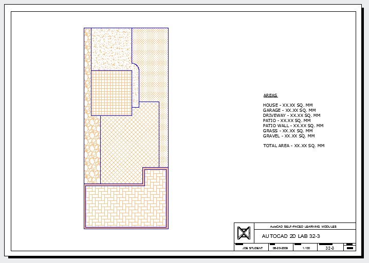
Lab Exercise 32-3
Time allowed: 80 minutes.
| Drawing Name | Template | Units |
|---|---|---|
| AutoCAD 2D Lab 32-3 | 2D Layout Metric | Millimeters |
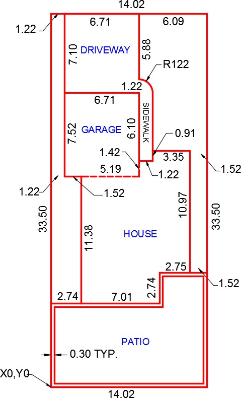
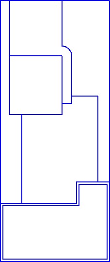
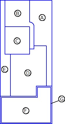
Step 1
Using the dimensioned drawing as a reference, on layer: Lot Lines, draw only the four outside lot lines or the boundary of the lot. The dimensions on the drawing are in meters but the input is in millimeters so you must be careful. 1 meter = 1000 millimeters (Figure Step 1A and 1B)

Step 2
Using the dimensioned drawing as a reference, on layer: Object, draw the lines and arcs of the driveway, garage, house and patio. (Figure Step 2)
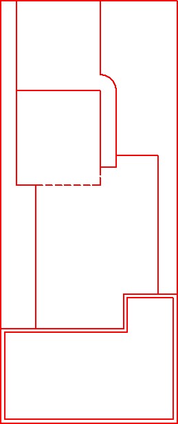
Step 3
On layer: Boundary, use the BOUNDARY command to create a closed pline around each of the seven areas shown in the figure. (Figure Step 3)
Step 4
Turn layer: Object off.
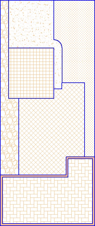
Step 5
On layer: Lot Hatch, insert the hatch patterns in the seven areas as follows:
A Grass
B AR-CONC
C Net
D Net – at an angle of 45 degrees
E Gravel
F AR-HBONE
G Solid
(Figure Step 5A and 5B)
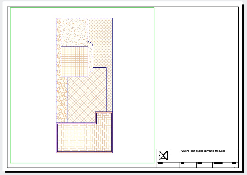
Step 6
Enable layout: Module Layout A2. On layer: Viewport, create a viewport and set the scale to 1:100 (0.01). (Figure Step 6)
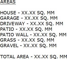
Step 7
Find the areas and of the seven areas. Set the text style to:2D Modules. In Paper space, on layer: Text, insert the text as shown in the figure and include your answers. Set an appropriate text height. (Figure Step 7)
Step 8
On layer: Titleblock Text, fill in the titleblock using the standard shown in Module 20.
Step 9
Turn layer: Viewport off. (Figure Step 9)
Step 10
Save and close the drawing.
