Module 8: Object Snap
Learning Outcomes
- Describe object snap, AutoSnap, and manual object snap modes.
- List the object snap modes for a line, a circle, and an arc.
- Apply the OSNAP command to set the object snap modes for AutoSnap.
- Describe how to enable and disable object snap and its importance when creating drawings.
- Use object snap to complete drawings.
Object Snap
Object snap allows you to immediately locate and attach to predefined object snap modes (locations) on existing drawing objects. All drawing objects have at least one object snap mode. In this module, the object snap modes for the drawing objects line, circle, and arc are taught. Many more will be taught throughout the AutoCAD 2D book.
Using object snap allows you to draw quickly and accurately using the existing geometry in the drawing. This is done without having to know the coordinate locations of those objects. Object snap is one of the most important features in any CAD system.
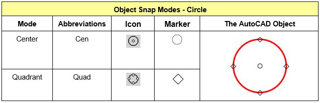
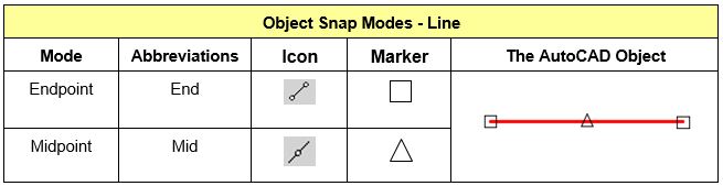
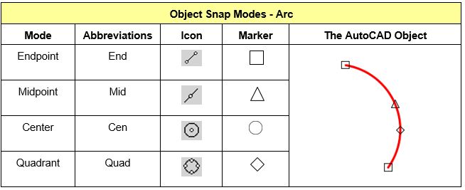
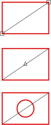
Study Figure 8-1, 8-2, and 8-3. They show the object snap modes and their locations for a line, a circle, and an arc. A line has 3 snap mode locations that can be snapped to while circles and arcs have 5 each. When requested, AutoCAD can find and snap to these exact locations.
AutoSnap
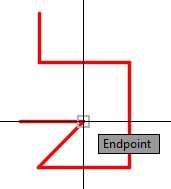
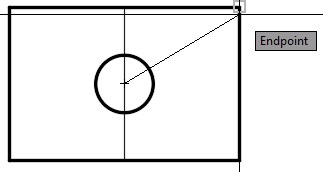
AutoSnap is a visual aid to help you see and use object snap modes (locations) more efficiently. It allows you to set the object snap modes that AutoSnap will find automatically when object snap is enabled. Object snap can be enabled or disabled anytime by pressing F3. While a command is active, AutoSnap displays a marker and a tool tip when the cursor is moved over an object snap mode location that it has been set to find. In Figure 8-4, AutoSnap is indicating that it found the endpoint of the line. Note that the Graphic cursor does not have to be located exactly at the endpoint of the line. It only has to be close.
Geometry Lesson: Finding the Center of a Square or Rectangle
Using geometry, the center of a square or a rectangle can easily and accurately be located without knowing its size or doing any math. To do this, either one of the following methods can be used.
Method 1
Step 1
Draw a construction line between any two diagonal corners by snapping to the endpoints.
Step 2
The midpoint of the construction line that you inserted in Step 1 is the center of the square or rectangle.
Step 3
In this step, a circle is inserted at the midpoint of the line. The circle is located exactly in the center of the square or rectangle.
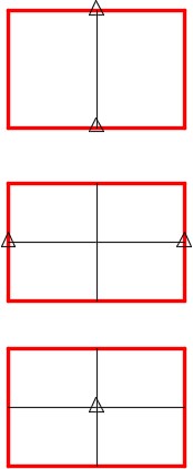
Method 2
Step 1
Draw a line between the midpoints of two opposite sides of the rectangle or square.
Step 2
Draw another line between the midpoint of the other opposite sides of the rectangle or square.
Step 3
The midpoint of either line and the intersection of the two lines is the center of the rectangle or square. Actually, one line would have been enough to find the center.
Geometry Lesson: Using Construction Objects
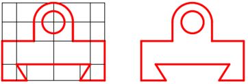
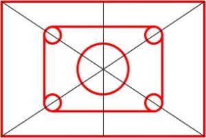
The best way to construct most drawings is to draw construction objects as an aid. There will be more and more drawings like this in future lab exercises. Construction objects are objects that are drawn by you to be used for construction only and will not be part of the finished drawing. It is important to save those objects for later use or to see how the construction was preformed.
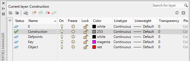
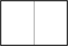
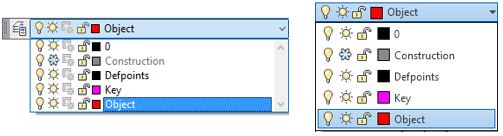
From this point forward, in all workalongs and lab exercises, create a layer and name it Construction, color 253. Draw all construction objects on this layer and do not delete them. When you complete the drawing, freeze layer Construction. When required, simply thaw layer Construction to display the construction objects. See Figure 8-5. The drawing on the left has layer Construction thawed while the drawing on the right has layer Construction frozen.
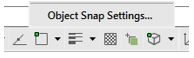
Construction Objects
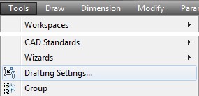
AutoCAD Command: OSNAP
The OSNAP command is used to open the Drafting Settings dialogue box which allows you to set object snap mode defaults for Autosnap. The function key F3 toggles osnap off and on.
Shortcut: OS
WORKALONG: Using Object Snap
Step 1
Start a new drawing using the template: 2D English.
Step 2
Save and name the drawing: AutoCAD 2D Workalong 08-1.
Step 3
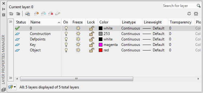
Create layer: Object, color red and layer: Construction, color 253. (Figure Step 3)
Step 4
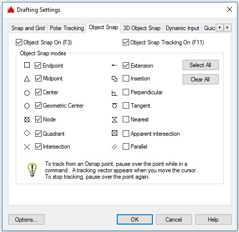
Enter the OSNAP command to open Drafting Settings dialogue box.
Step 5
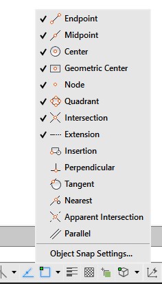
Step 4 will open the Drafting Settings dialogue box. Enable the Object Snap tab. In the Object Snap modes area, enable the modes to match the figure. Click OK to close the dialogue box. (Figure Step 5)
Step 6
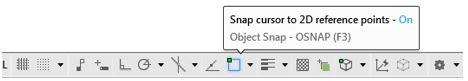
Enable object snap by pressing the function key F3. Notice how the Object Snap icon in the Status bar will display enabled as shown in Figure Step 6A. Press F3 again and note how the Object Snap icon displays disabled as shown in Figure Step 6B.


Step 7
Set layer: Construction as the current layer. (Figure Step 7)
Step 8
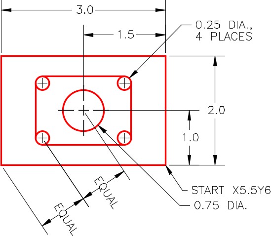
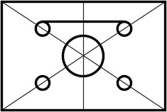
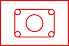
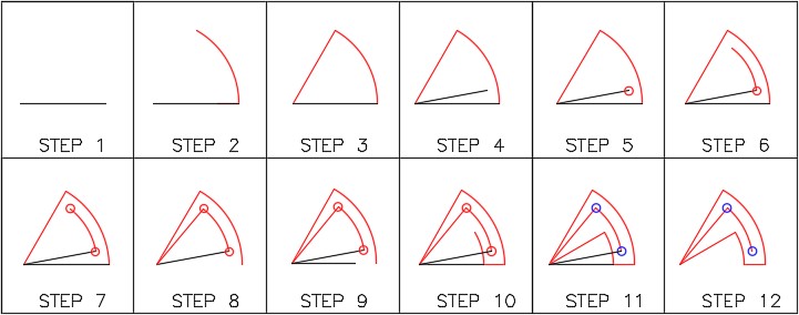
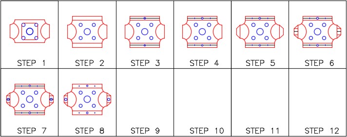
Using the dimensioned drawing as a reference, enter the LINE command and draw the 4 lines to form the outer rectangle. (Figure Step 8A and 8B)

Step 9
Press F3 to enable object snap. Check to ensure that it is enabled by checking its status in the Status bar.
Step 10
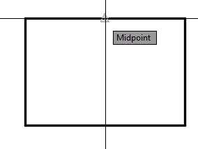
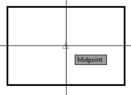
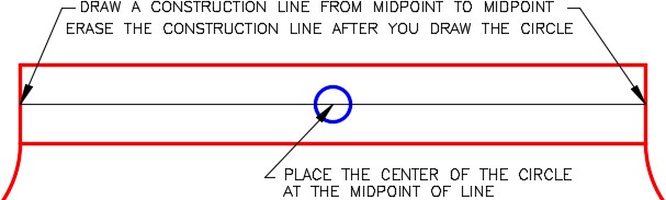
Enter the LINE command and move the cursor on the top horizontal line. Move it approximately to the midpoint of the line. When the AutoSnap marker displays the midpoint icon and the tool tip, pick it. Figure Step 10)
Step 11
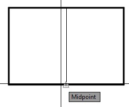
Move the cursor to the bottom horizontal line and do the same as Step 10. Press Enter to exit the command. You now have a vertical line from the midpoint of the top line to midpoint of the bottom line. (Figure Step 11A and 11B)
Step 12
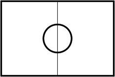
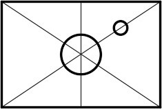
Enter the CIRCLE command. To locate the center of the circle, move the cursor to the midpoint of the vertical line that you drew in Step 11. When the midpoint icon and the tool tip displays, pick it. Enter a D, for diameter, and then 0.75 to complete the circle. (Figure Step 12A and 12B)
Step 13
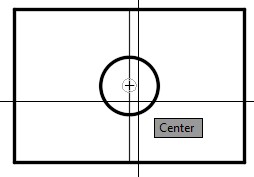
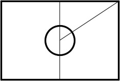
Enter the LINE command and for the first point snap to the center of the circle. For the second point, snap to the endpoint in the top right corner. (Figure Step 13A, 13B, and 13C)
Step 14
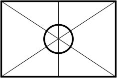
Repeat Step 13 three additional times to draw 3 lines from the center of the rectangle to each of the corners of the rectangle. (Figure Step 14)
Step 15
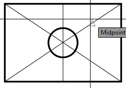
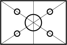
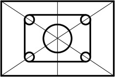
Enter the CIRCLE command. For the center location of the circle, snap to the midpoint of one of the diagonal lines. Enter the radius of 0.125 or the diameter of 0.25. (Figure Step 15A and 15B)
Step 16
Repeat Step 15 three times to draw a circle at the midpoint of each inclined line. (Figure Step 16)
Step 17
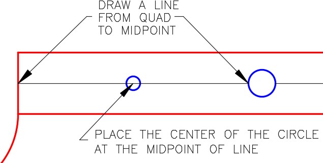
Enter the LINE command and for the first point, snap to the top quadrant of the top left circle. For the second point, snap to the top quadrant of top right circle. (Figure Step 17A, 17B, and 17C)
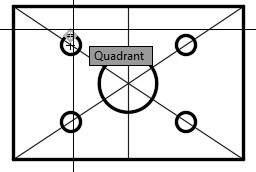
Step 18
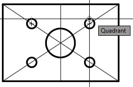
Repeat Step 17 three additional times to draw 3 more lines. Ensure that you snap to the quadrant of the circle to locate the end of each line. (Figure Step 18)
Step 19
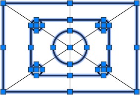
Without entering a command, individually select the objects that you want to reside on layer Object. While the objects are selected, pull down the Layer toolbar list and click layer: Object. After you select the name, click inside the Graphic window and then press Esc to clear the selected objects. (Figure Step 19A and 19B)
Step 20
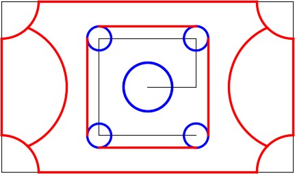
Pull down the layer list again and freeze layer: Construction. Your drawing is complete and should appear as shown in the figure. (Figure Step 20A and 20B)
Step 21
Save and close the drawing.
Manual Object Snap Modes
Object snap modes can be entered manually inside any command that uses them. This can be a handy feature for modes that are not used very often and are not enabled in AutoSnap. It also overrides the current settings to force AutoCAD to find the snap mode you entered. i.e.
Command: LINE
Specify first point: end of
(Inside the LINE command, you must start the next line at the end of an existing Line. Instead of using AutoSnap, enter the mode end on the keyboard to AutoCAD’s prompt. When a line is picked, AutoCAD will snap to the closest endpoint on that line.)
or
Command: CIRCLE
Specify center point for circle or [3P/2P/Ttr (tan tan radius)]: mid of
(In the CIRCLE command, the snap mode mid is entered and AutoCAD responds of. Pick an existing object and AutoCAD will snap to its midpoint.)

Key Principles
Key Principles in Module 8
- Object snap is one of the most important features in any CAD system. Use object snaps to quickly and accurately draw using existing geometry in the drawing.
- The function key F3 toggles object snap between enabled or disabled.
- Use geometry and object snap rather than math to find the centers of squares or rectangles.
- Disable object snap when you are not using it.
- Draw construction objects on layer Construction and freeze that layer after you complete the drawing.
- You can override or force AutoCAD to snap to an object snap location on an object by manually entering the osnap mode in the command line.
Lab Exercise 8-1
Time allowed: 30 minutes.
| Drawing Name | Template | Units |
|---|---|---|
| AutoCAD 2D Lab 08-1 | 2D English | Inches |
| Layer Name | Objects on Layer | Color |
|---|---|---|
| Construction | Construction objects | 253 |
| Object 1 | All lines and arcs | Red |
| Object 2 | All circles | Blue |
Step 1
Start a new drawing using the template shown above.
Step 2
Setup the layers using the Layering Scheme shown above.
Step 3
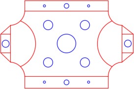
Draw the object shown in the figure using the layering scheme. In this drawing, place the lines and arcs on layer: Object 1 and the circles on layer: Object 2. Lines and arcs should display red and the circles should display blue. (Figure Step 3A and 3B)
Completed Drawing
Step 4
Enter the UNITS command. In the Units dialogue box, set the Insertion Units to Inches.
Step 5
Check the drawing’s accuracy with the key.
Step 6
If there are any errors, turn layer Key off and correct the drawing. If necessary, start a new drawing and draw it again.
Step 7
Turn layer Key on. If the drawing still inaccurate, go back to Step 6.
Step 8
Turn layer Key off.
Step 9
Save and close the drawing.
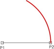
Hint 1
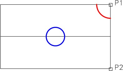
Use object snap modes and snap to as many locations as possible rather then entering XY coordinates on the keyboard. (Figure Hint 1)
Command: ARC
Specify start point of arc or [Center]: C
Specify center point of arc: (end) P1
Specify start point of arc: (end) P2
Specify end point of arc or [Angle/chord Length]: A
Specify included angle: 60
Command:
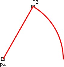
Hint 2
Use object snap modes and snap to as many locations as possible rather then entering XY coordinates on the keyboard. (Figure Hint 2)
Command: LINE
Specify first point: (end) P3
Specify next point or [Undo]: (end) P4
Specify next point or [Undo]:
Command:
Hint 3
There should be two construction objects in this drawing. (Figure Hint 3)
Lab Exercise 8-2
Time allowed: 40 minutes.
| Drawing Name | Template | Units |
|---|---|---|
| AutoCAD 2D Lab 08-2 | 2D English | Inches |
| Layer Name | Objects on Layer | Color |
|---|---|---|
| Construction | Construction objects | 253 |
| Object 1 | All lines and arcs | Red |
| Object 2 | All circles | Blue |
Step 1
Start a new drawing using the template shown above.
Step 2
Setup the layers using the Layering Scheme shown above.
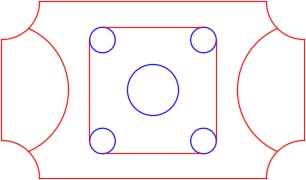
Completed Drawing
Step 3
Draw the object shown below using the layering scheme. In this drawing, place the lines and arcs on layer: Object 1 and the circles on layer: Object 2. The lines and arcs should display red and the circles blue. (Figure Step 3A and 3B)
Step 4
Enter the UNITS command. In the Units dialogue box, set the Insertion Units to Inches.
Step 5
Check your drawing with the key. The key name is the same as the drawing name.
Step 6
If you have any errors, turn layer Key off and correct your drawing. If you cannot correct it, start it over from the beginning.
Step 7
Turn layer Key on to check your drawing. If it is still inaccurate, go back to Step 6.
Step 8
Turn layer Key off and freeze layer: Construction
Step 9
Save and close the drawing.
Hint 1
The arcs on the corners can be drawn using the command shown below. (Figure Hint 1)
Command: ARC
Specify start point of arc or [Center]: C
Specify center point of arc: (end) P1
Specify start point of arc: @-1.5,0
(This sets the radius and the direction of the start point.)
Specify end point of arc or [Angle/chord Length]: (end) P2
Command:
(Repeat on the other three corners. Keep in mind that arcs are constructed counterclockwise in AutoCAD.)
Hint 2
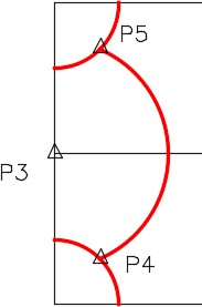
The arcs on the sides can be drawn using the command shown below. (Figure Hint 2)
Command: ARC
Specify start point of arc or [Center]: C
Specify center point of arc: (mid) P3
Specify start point of arc: (mid) P4
Specify end point of arc or [Angle/chord Length]: (mid) P5
(Do the same on the other side. Ensure that you construct the arc counterclockwise.)
Command:
Hint 3
The figure shows the construction objects in this drawing. (Figure Hint 3)
Lab Exercise 8-3
Time allowed: 40 minutes.
| Drawing Name | Template | Units |
|---|---|---|
| AutoCAD 2D Lab 08-3 | N/A | Inches |
| Layer Name | Objects on Layer | Color |
|---|---|---|
| Construction | Construction objects | 253 |
| Object 1 | All lines and arcs | Red |
| Object 2 | All circles | Blue |
Step 1
Open the drawing: AutoCAD 2D Lab 08-2.
Step 2
Using the SAVEAS command, save it with the name: AutoCAD 2D Lab 08-3.
Step 3
Turn off all the layers except for layer: Key. If the magenta key from Lab 08-2 displays, select it and press the delete key. Turn all of the other layers back on.
Step 4
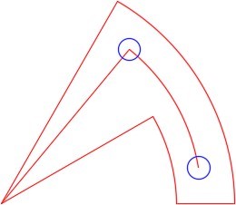
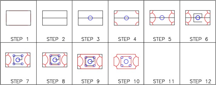
Complete the object by adding and erasing objects to match the figure. (Figure Step 4A and 4B)
Completed Drawing
Step 5
Enter the UNITS command. In the Units dialogue box, set the Insertion Units to Inches.
Step 6
Check your drawing with the key. The key name is the same as the drawing name.
Step 7
If you have any errors, turn layer Key off and correct them.
Step 8
Turn layer Key off and freeze layer Construction
Step 9
Save and close the drawing.
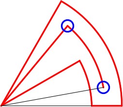
Hint 1
Locate the larger circle as shown in the figure. (Figure Hint 1)
Hint 2
Locate the smaller circle as shown in the figure. (Figure Hint 2)
Hint 3
The figure shows the construction objects in this drawing. (Figure Hint 3)
Lab Exercise 8-4
Time allowed: 40 minutes.
| Drawing Name | Template | Units |
|---|---|---|
| AutoCAD 2D Lab 08-4 | 2D English | Inches |
| Layer Name | Objects on Layer | Color |
|---|---|---|
| Gasket | All drawing objects | Blue |
Step 1
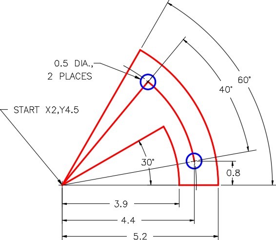
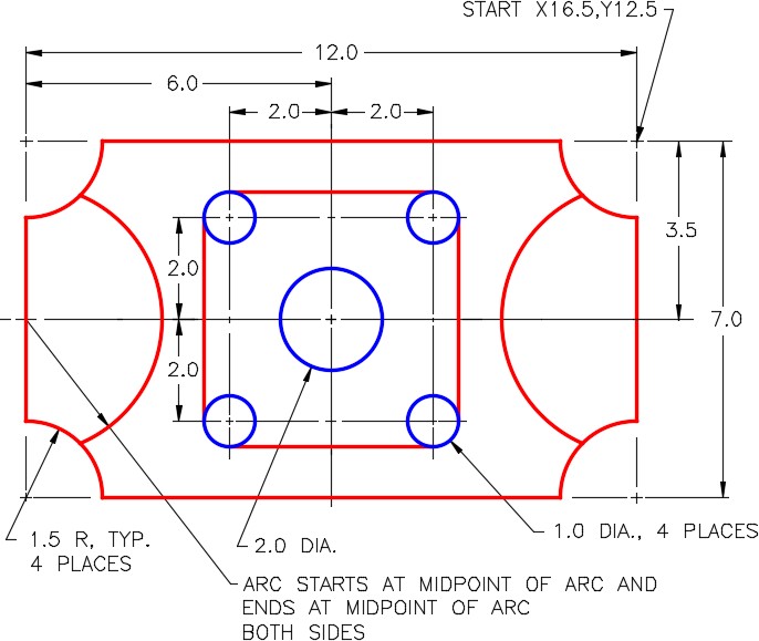
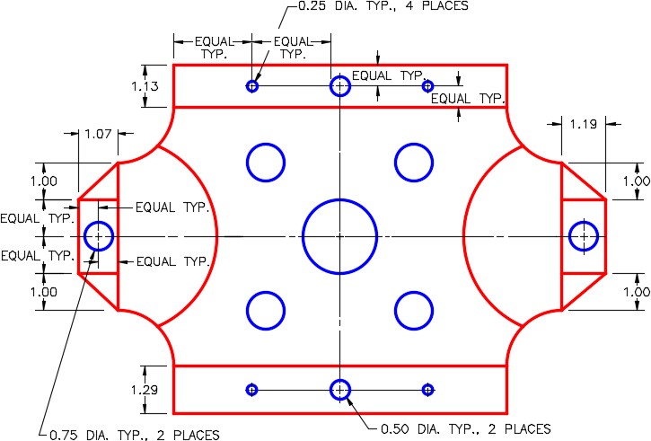
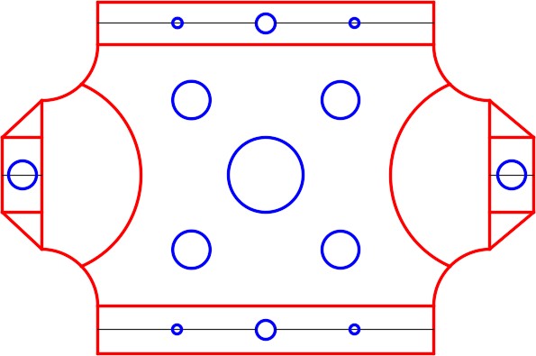
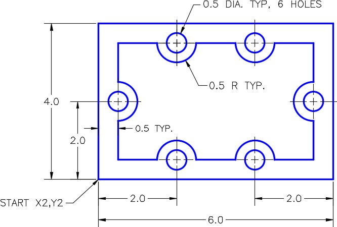
Draw the top view of the simple gasket shown in the dimensioned drawing using the layering scheme. (Figure Step 1A, 1B, and 1C)
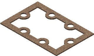
Simple Gasket
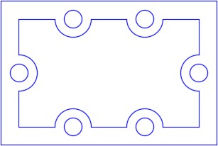
Completed Drawing
Step 3
Set the insertion units and check your drawing with the key. Turn layer Key off and freeze layer Construction.
Step 4
Save and close the drawing.
