Module 24: Scaling and Stretching
Learning Outcomes
When you have completed this module, you will be able to:
- Describe how drawing objects are stretched and scaled to change their original shape and size.
- Apply the STRETCH and SCALE commands to change the size and shape of existing objects by stretching or scaling them.
Stretching Objects
The STRETCH command has many uses. Using this command is a good way to edit the shape of objects without having to erase and redraw portions of them as shown in Figure Step 24-1. Existing objects can be stretched larger or smaller.
The objects to be stretched MUST be selected using a crossing or cross polygon window. The objects that are totally inside the crossing or cross polygon window are moved and the objects that cross the window are stretched.
Scaling Objects
The SCALE command can be also be used in many ways. An object can be scaled either larger or smaller by using a scale factor or by using a reference and letting AutoCAD calculate the scale factor. See Figure 24-2. The object to be scaled is scaled around a base point.
The base point is the only location that does not change as the object is scaled around it.

Scaling
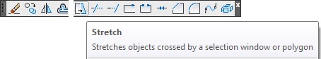
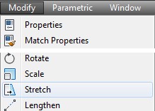
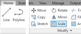
AutoCAD Command: STRETCH
Shortcut: S
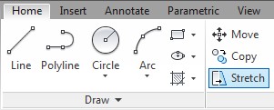
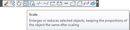
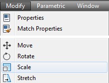
AutoCAD Command: SCALE
The SCALE command is used to scale drawing objects, around a base point, either larger or smaller.
Shortcut: SC
WORKALONG: Stretching and Scaling Objects
Step 1
Start a new drawing using the template: 2D Layout English.
Step 2
Save and name the drawing: AutoCAD 2D Workalong 24-1.
Step 3
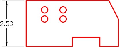
On layer: Object, draw the object shown in the figure. (Figure Step 3)
Step 4
Enter the STRETCH command, as shown below, to stretch the object longer. (Figure Step 4A and 4B)
Command: STRETCH
Select objects to stretch by crossing-window or crossing-polygon…
Select objects:
Specify opposite corner: 4 found
(Use a crossing window and locate it as shown in the figure. You MUST use a crossing window in the STRETCH command.)
Select objects:
Specify base point or [Displacement] <Displacement>: 0,0
Specify second point or <use first point as displacement>: @1,0
(The lines that the crossing window cross are stretched 1 unit longer in the positive X direction. The lines totally inside the crossing window are moved 1 unit in the positive X direction.)
Command:
Step 5
Enter the STRETCH command, as shown below, to stretch the object higher. (Figure Step 5A and 5B)
Command: STRETCH
Select objects to stretch by crossing-window or crossing-polygon…
Select objects:
Specify opposite corner: 4 found
(Use a crossing window and locate it as shown in the figure)
Select objects:
Specify base point or [Displacement] <Displacement>: 0,0
Specify second point or <use first point as displacement>: @0,1.5
(The lines that the crossing window cross are stretched 1.5 units in the positive Y direction and the lines and circles that are totally inside the crossing window are moved 1.5 units in the positive Y direction.)
Command:
Step 6
Enter the STRETCH command, as shown below, to stretch the object. (Figure Step 6A, 6B, and 6C)

Command: STRETCH
Select objects to stretch by crossing-window or crossing-polygon…
Select objects:
Specify opposite corner: 3 found
(Use a crossing window and locate it as shown in the figure.)
Select objects:
Specify base point or [Displacement] <Displacement>: (end)
(Snap to the end of the line.)
Specify second point or <use first point as displacement>: @1,0
(The lines that the crossing window crosses are stretched 1 unit, one longer and one shorter. The three lines inside the crossing window are moved 1 unit in the positive X direction.)
Command:


Step 7
Using what you already learned, use the STRETCH command to stretch the object to match Figure Step 7A. See Figure Step 7B for the location of the cross polygon window that you have to use. (Figure Step 7A, 7B, and 7C)
Step 8
Using what you already learned, use the STRETCH command to stretch the object to match Figure Step 8A. See Figure Step 8B for the location of the cross polygon window that you have to use. (Figure Step 8A, 8B, and 8C)
Step 9
Using what you already learned, use the MIRROR command to mirror the object to match Figure Step 9A. (Figure Step 9A and 9B)
Step 10
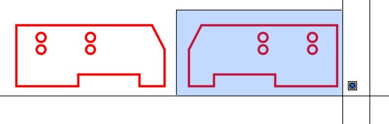
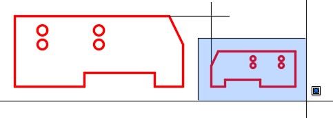
Enter the SCALE command, as shown below, to scale the object on the right by a scale factor of 0.5. (Figure Step 10A, 10B, and 10C)
Command: SCALE
Select objects:
Specify opposite corner: 13 found
(Select the objects to be scaled in a window.)
Select objects:
Specify base point: (end)
(Snap to the end of bottom left line to establish the base point. This point will remain at the same location and the remainder of the object will be scaled.)
Specify scale factor or [Copy/Reference] <1.0000>: 0.5
(Scale the object by a scale factor of one-half.)
Command:
Step 11
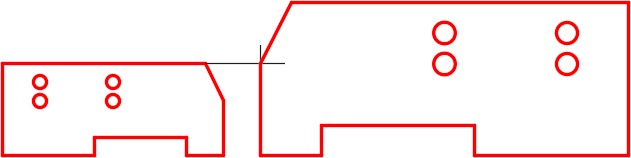
On layer: Construction, enable Ortho mode and draw two lines. Snap to the endpoints of existing lines, as shown in the figure, drawing one vertical line and one horizontal line. The length of the lines is not important but they must intersect. (Figure Step 11)
Step 12
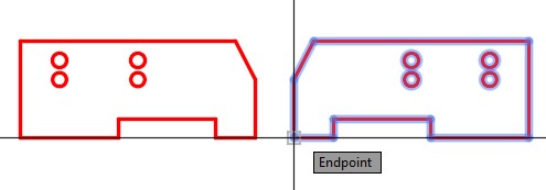
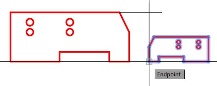
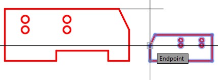
Enter the SCALE command, as shown below, to scale using the Reference option. (Figure Step 12A, 12B, 12C, 12D, and 12E)
Command: SCALE
Select objects:
Specify opposite corner: 13 found
(Select the object on the right using a window as shown Figure Step 12A.)
Select objects:
Specify base point: (end)
(Snap to the end of the line for the base point.)
Specify scale factor or [Copy/Reference] <1.5000>: R
(Use a Reference.)
Specify reference length <1.0000>: (end)
Specify second point: (end)
(Specifying a reference length.)
Specify new length or [Points] <1.0000>: (end)
(Specifying the new length of the reference length.)
Command:

Step 13
Save and close the drawing.
WORKALONG: Rotating and Scaling Objects
Step 1
Start a new drawing using the template: 2D Layout English.
Step 2
Save and name the drawing: AutoCAD 2D Workalong 24-2.
Step 3
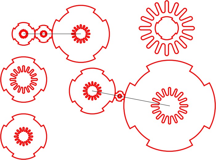
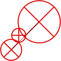
On layer: Object, draw the object shown in the figure. (Figure Step 3)
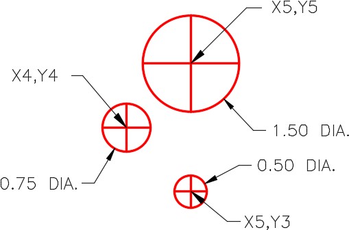
Step 4
On layer: Construction, draw a line from center of the large circle to the center of the medium circle as shown in the figure. (Figure Step 4).
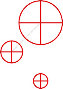
Step 5
Using the ROTATE command, rotate the large circle, using the Reference option, to line up the quad lines with the construction line. (Figure Step 5).
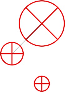
Step 6
Using the ROTATE command, rotate the medium size circle, using the Reference option, to line up the quad lines with the construction line. (Figure Step 6).
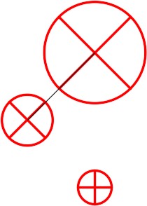
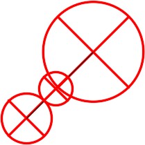
Step 7
Using the MOVE command, move the small circle snapping the bottom quad to the intersection of the medium circle and the construction line. (Figure Step 7)
Step 8
Using the ROTATE command, rotate the small circle, using the Reference option, to line up the quad lines with the construction line. (Figure Step 8)
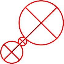
Step 9
Using the SCALE command, scale the small circle, using the Reference option, to fit exactly between the other two circles. (Figure Step 9)
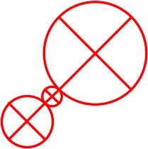
Step 10
Freeze layer: Construction. Your completed drawing should appear as shown in the figure. (Figure Step 10)
Step 11
Save and close the drawing.
Key Principles
Key Principles in Module 24
- The STRETCH command requires that a crossing or cross polygon window be used to select the objects. It moves the objects that are totally inside the window and stretches the objects that cross the window. You MUST use a crossing or cross polygon window at all times with the STRETCH command.
- The SCALE command can scale an object either larger or smaller by using a scale factor or a reference and let AutoCAD calculate the scale factor. The objects to be scaled is scaled around a base point. The base point is the only location that does not change as the objects are scaled around it.
- A scale factor of 0.5 scales the object by one-half its height and one-half its width and therefore scales the object one-quarter of its original size.
Lab Exercise 24-1
Time allowed: 45 minutes.
| Drawing Name | Template | Units |
|---|---|---|
| AutoCAD 2D Lab 24-1 | 2D Layout English | Inches |
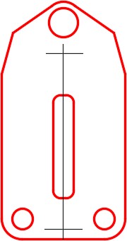
Step 1
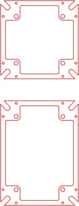
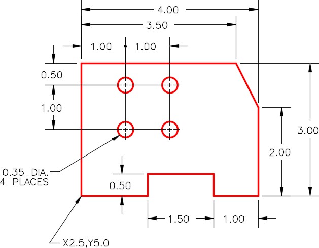
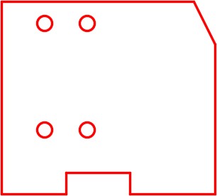
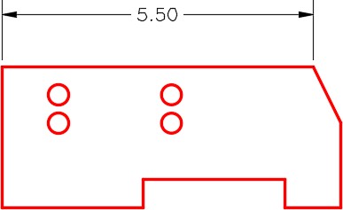
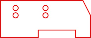
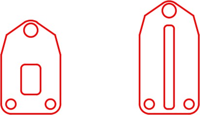
On layer: Object, draw the object shown in the figure. (Figure Step 1A and 1B)
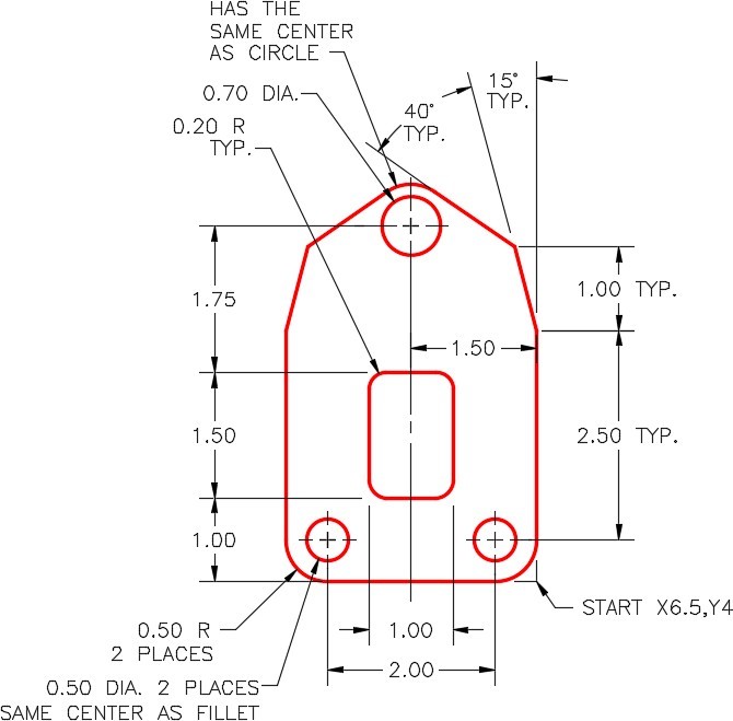
Completed Drawing
Step 2
Set the insertion units and insert the key. Check your drawing for accuracy.
Step 3
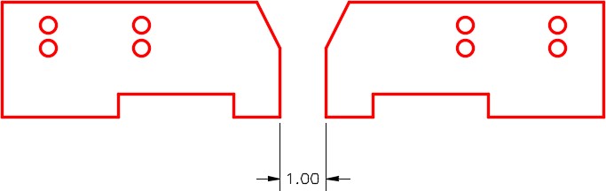
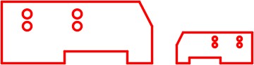
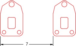
Copy the completed object 7 inches in the positive X direction. (Figure Step 3)
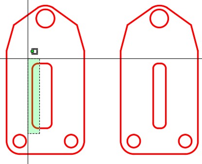
Step 4
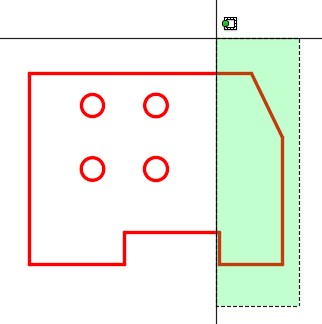
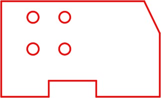
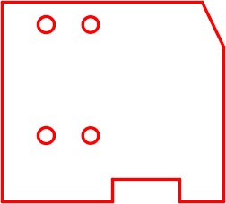
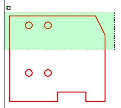
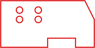
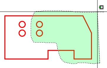
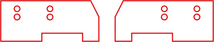
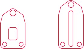
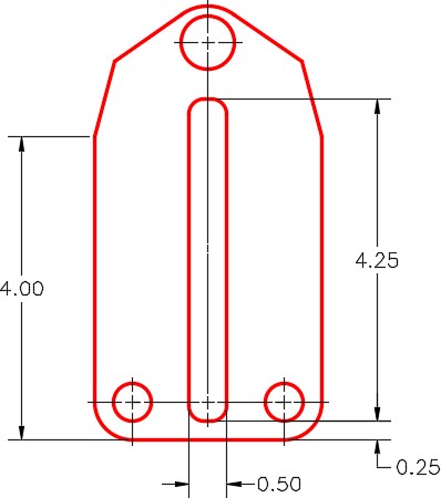
Using the STRETCH command only, edit the object on the right to match the figure. (Figure Step 4A and 4B)
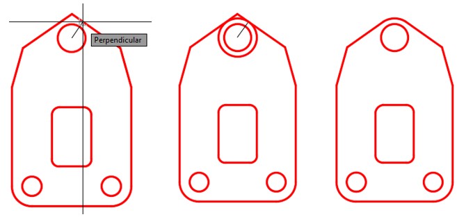
Hint 1
To draw the arc at the top, draw a construction line by snapping the first point to the center of the circle and the second point snapping it perpendicular to the inclined line. Draw a circle, on layer: Object, snapping to the center of the circle for the center point and the end of the construction line for the radius. Trim the circle. (Figure Hint 1)
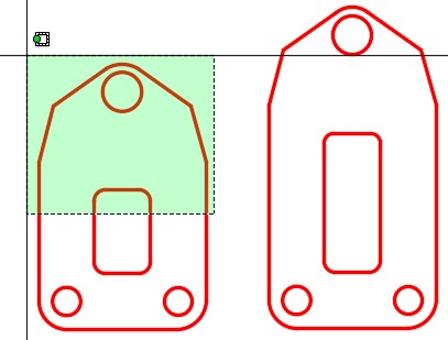
Hint 2
See the following steps to edit the object using the STRETCH command.
Step 1
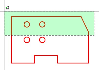
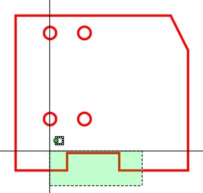
Stretch the object 1 inch in the positive Y direction. (Figure Hint 2 – Step 1)
Step 2
Stretch the right side of the slot 0.25 inches towards the center. (Figure Hint 2 – Step 2)
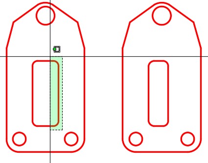
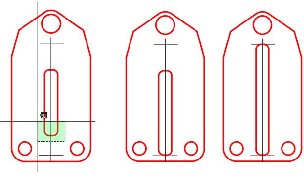
Step 3
Stretch the left side of the slot 0.25 inches towards the center. (Figure Hint 2 – Step 3)
Step 4
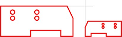
Draw construction lines using the dimensioned drawing in Step 1 as a reference. (Figure Hint 2 – Step 4)
Step 5
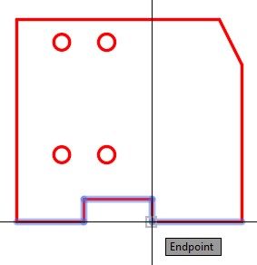
Stretch the bottom of the slot using the construction lines to snap to. Do the same for the top of the slot. (Figure Hint 2 – Step 5)
Lab Exercise 24-2
Time allowed: 60 minutes.
| Drawing Name | Template | Units |
|---|---|---|
| AutoCAD 2D Lab 24-2 | 2D Layout English | Inches |
Step 1
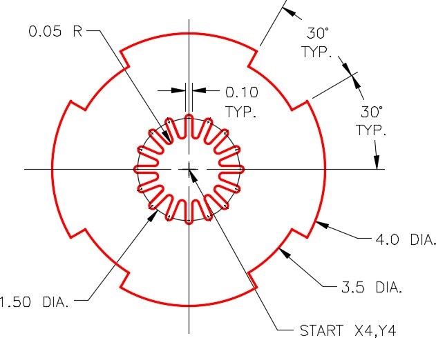
On layer: Object, draw the object shown in the figures. This object will be referred to as the original object in this lab exercise. (Figure Step 1A and 1B)
Completed Drawing
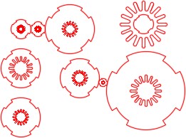
Step 2
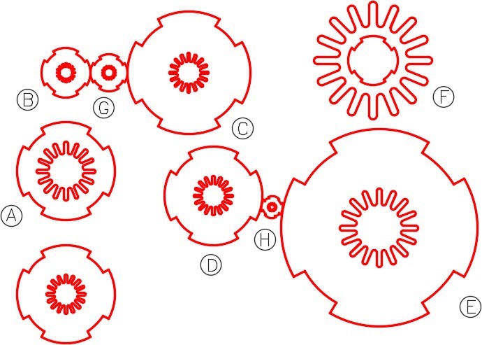
Copy and scale the original object in steps A to H: (Figure Step 2)
A Copy the center to X4,Y9. Scale the inside array only. Use the scale factor of 1.5. Use the center as base point.
B Copy the center to X4,Y13. Scale the whole object at a scale factor of 0.5. Use the center as base point.
C Copy the center to X9,Y13. Scale the outside array only. Use a scale factor of 1.25 Use the center as base point.
D Copy the center to X10,Y8.
E Copy the center to X16.75,Y6.7. Scale the whole object at a scale factor of 2. Use the center as base point.
F Copy the center to X16.5,Y13.5. Scale the inside array only at a scale factor of 3. Scale the outside array at a scale factor of 0.5. Use the center as the base point.
G Copy the object and scale it to fit exactly between the existing objects B and C. Scale it to fit exactly between the midpoint on the arcs. Use the Reference option do not use math.
H Copy the object and scale it to fit exactly between the closest distance between the two existing objects D and E. Rotate the object so the midpoints of the arcs are touching the existing objects. Use the Reference option. Do not use math.
Hint 1
Using the dimensioned drawing, complete the following steps:
Step 1
Draw 2 lines and an the arc.
Step 2
Array them 16 times.
Step 3
Deleted unwanted objects and insert two 0.05 radius fillets.
Step 4
Deleted the unnecessary objects.
Step 5
Array it 16 times.
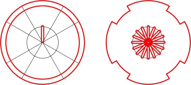

Hint 2
Draw construction lines from center to center of the objects to help you complete the drawing. (Figure Hint 2)