Module 27: Multiview Drawings
Learning Outcomes
When you have completed this module, you will be able to:
- Describe a multiview drawing, the glass box principle, the three standard views, object lines, and hidden lines.
- From a 3D pictorial of an object, draw a multiview drawing using the three standard views.
NOTE: If you understand multiview drawings, hidden lines, and can draw the three standard views of an object skip this module and go directly to Module 28.
Multiview Drawing
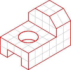
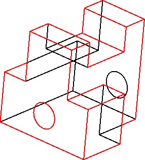
The drafting and design world uses a system of representing a three- dimensional object by drawing two-dimensional views. It is called a multiview drawing. To explain this system of drawing, the 3D wireframe model shown in Figure 27-1 will be used. To draw a two- dimensional view of one side of the object, place a imaginary plane parallel to its side and project the view of the model (perpendicular) onto the plane. This is called orthographic projection. Imagine the plane to a sheet of glass. See Figure 27-2.
Three Dimensional Wireframe Model

Projecting the Two-Dimensional View
The Glass Box Principle
To carry this principal further, place a plane on each side of the object for a total of six planes or sheets of glass to form a glass box. See Figure 27-3. Picture unfolding the glass box onto a flat two-dimensional plane as shown in Figure 27-4.
All six views are now visible at the same time. The six views are named Top, Front, Right Side, Left Side, Rear, and Bottom.
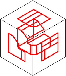
The Glass Box Principle
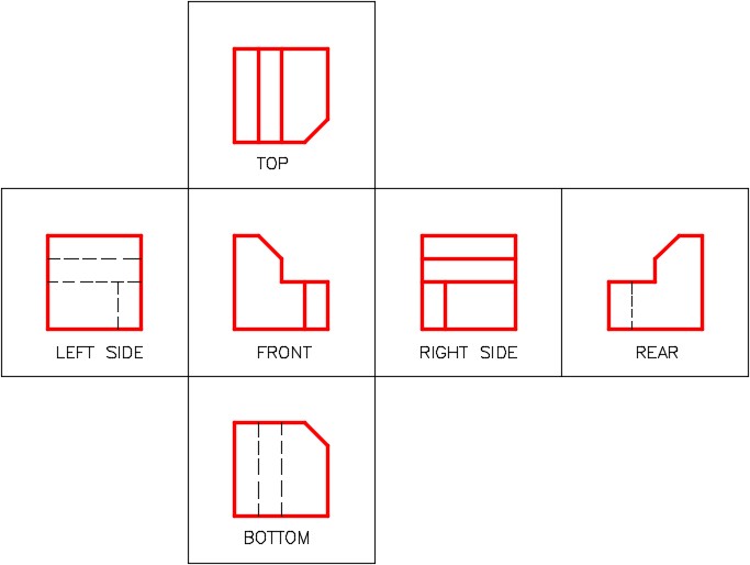
The Glass Box Unfolded
The Three Standard Views
In almost all objects, three views are adequate to describe it. In fact, there are many models that only need two views and some that only need one view to describe them.
The three standard views are the Top, Front, and Right Side. They must be drawn in the positions shown in Figure 27-5 and must align.
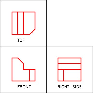
The Three Standard Views
Picking the Standard Three Views
The three standard views are always selected as shown in Figure 27-6.
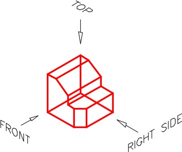
Picking the Three Standard Views
Drawing the Views
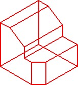
Usually it is best to draw the view with the most irregular shape first and then project lines to the other two views. For the object in Figure 27-7, the front view should be drawn first and then the top and right side views are projected.
Notice how the views aligned. Figure 27-7 shows two different methods of projecting lines from the top view to the right side view or vise versa.
The distance between the views is not important and can be easily adjusted in AutoCAD using the MOVE command. In most cases, the distances are adjusted to accommodate dimensions and notes.
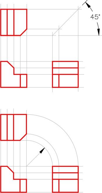
Two Methods for View Layout and Alignment
Drafting Lesson: Object and Hidden Lines
Lines and features that can be seen in the views are drawn with continuous or solid lines. They are called object lines. Even though they are called object lines, they can be circular in shape. To completely describe a model in a multiview drawing, you must also show all lines or features that are hidden in that view. They are called hidden lines and their linetype is dashed. Study the multiview drawing below and take note how the holes going through the object are shown with hidden lines. See Figures 27-8 and 27-9.
The Model
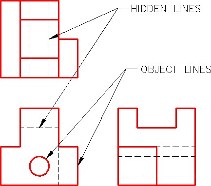
The Multiview Drawing of the Model
WORKALONG: Drawing Multiviews
Step 1
Start a new drawing using the template: 2D Layout English.
Step 2
Save and name the drawing: AutoCAD 2D Workalong 27-1.
Step 3
Set the insert units to inches. Open the Insert dialogue box and insert the block: AutoCAD 2D Workalong 27-1. (Figure Step 3)
Step 4
Using The EXPLODE command, as shown below, explode the block you just inserted. Command: EXPLODE
Select objects: 1found
(Select the grid)
Select objects:
Command:
Step 5
Lock layers: Grid and Border Lines. (Figure Step 5)
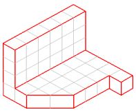
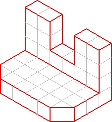
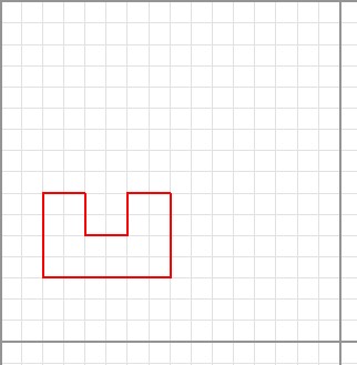
Step 6
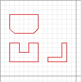
Draw in the upper left area. On layer Object, using the isometric drawing as the object to draw, draw the outline of the Front view of the model. (Figure Step 6A and 6B)
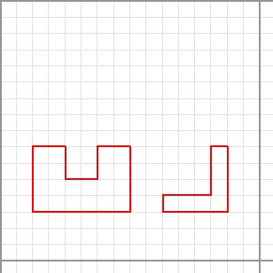
Step 7
Draw the outline of the Right Side view of the object. (Figure Step 7)
Step 8
Draw the outline of the Top view of the object. (Figure Step 8)
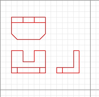
Step 9
Add the interior object lines in all views. (Figure Step 9)
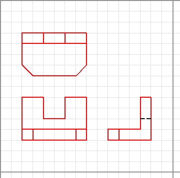
Step 10
On layer: Hidden, draw the hidden lines. In this drawing, only one line is required. (Figure Step 10)
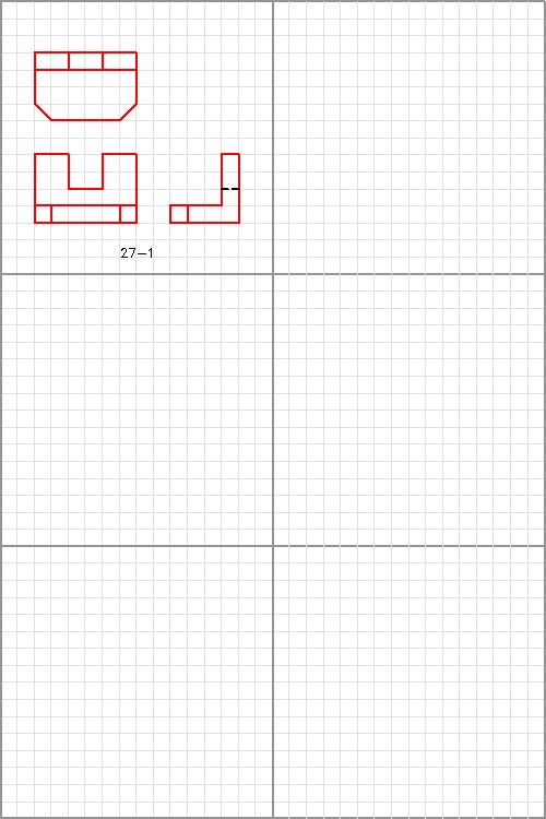
Step 11
On layer: Text, add the text 27-1 under the multiview drawing. Use text style: 2D Modules at a height of 0.5 inches. (Figure Step 11)

Step 12
Save and close the drawing.
Key Principles
Key Principles in Module 27
- The drafting and design world uses a system of representing a three-dimensional object by drawing two-dimensional views, called a multiview drawing.
- The three standard views of a multiview drawing are the top, front, and right side.
- When drawing a multiview drawing, the top, front and right side views of an object must be drawn in the correct position and must The distance between the views is not important.
Lab Exercise 27-1
Time allowed: 40 minutes.
Step 1
Open drawing: AutoCAD 2D Workalong 27-1. Using the SAVEAS command, save with the name: AutoCAD 2D Lab 27-1. (Figure Step 1)
Step 2
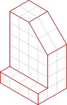
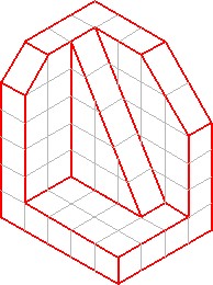
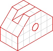
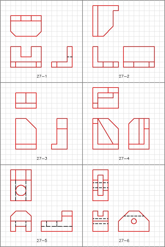
On layer: Object and Hidden, draw a multiview drawing using the standard three views of each of the five objects in Figure 27-2 to 27-6.
Step 3
Check your answer in Figure 27-7. Do not look at the answer until you have completed your drawings.