Module 17: Inquiry and Measurement
Learning Outcomes
When you have completed this module, you will be able to:
- Describe the geometry of a right angle triangle.
- Describe a point, point styles, and object snap mode node.
- Apply the system variable SNAPANG to rotate the graphic cursor.
- Apply the ORTHO, POINT, DIVIDE, and MEASURE commands.
- Apply the UNITS, DIST, and PROPERTIES commands to set the display units, make inquiries about drawing objects, measure distances, and angles.
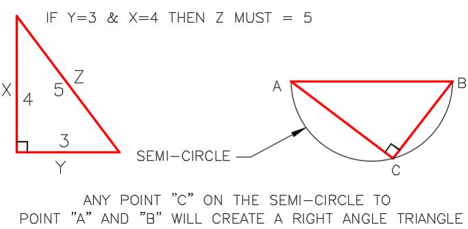
Geometry Lesson: A Right Angle Triangle
Figure 17-1 and 17-2 show the geometry of a right angle triangle. Understanding this theory will help you to complete your AutoCAD drawings.
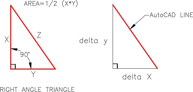
Geometry of a Right Angle Triangle
Geometry of a Right Angle Triangle
Geometry Lesson: Using Circles to Measure
When a measurement is required along an inclined line as shown in Step 1, Figure 17-3, the OFFSET command cannot easily be used to make that measurement. The best method of making the measurement is by drawing a construction circle with a 1 unit radius. Use the end of the inclined line as the center location for the circle. All points on the circumference of the circle will be the radius distance (1 unit) from the center of the circle as shown in the Step 2. Draw the 0.60 diameter circle locating its center at the intersection of the construction circle and the inclined line as shown in the Step 3.
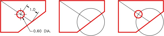
Figure 17-3
Using Circles to Measure
Points
A point is an AutoCAD drawing object that is one pixel in size. Its only geometry property is one XY coordinate.
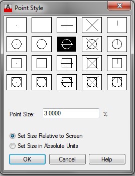
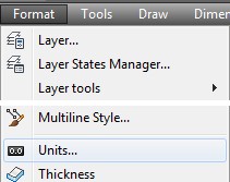
Point Style
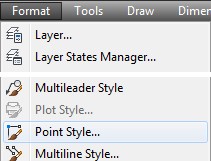
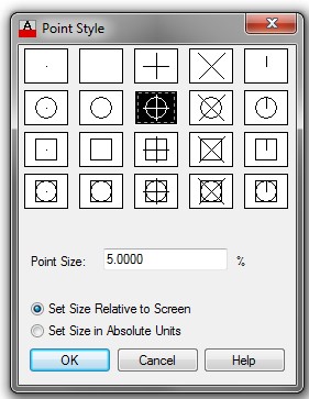
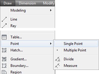
Since a point is nothing more then one pixel in size, it will not display very well in the drawing. If it is located under an existing drawing object, it will not be visible at all. Points can be set to display with an assigned style to make them easier to see and use. The point style for the current drawing is set with the Point Style dialogue box. To open the Point Style dialogue box, select Point Style in the Format Pull-down menu, See Figure 17-4 and 17-5. The size of the points can be set relative with the screen size or an absolute size. To display the points style at the correct size, when the point size is set relative to the screen, the drawing must be regenerated using the REGEN command.
Point Style
Point Style Dialogue Box
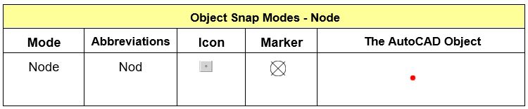
Object Snap Mode – Node
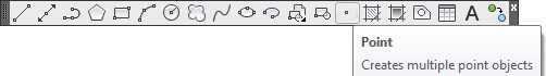
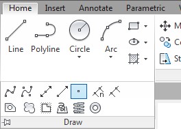
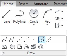
AutoCAD Command: POINT
The POINT command is used to insert a point.
Shortcut: PO
Rotating the Crosshairs
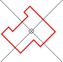
The crosshairs can be rotated to any angle. Its default rotation angle is 0 degrees, as shown in Figure 17-7. When the rotation angle is 0 degrees, the X axis is horizontal and the Y axis is vertical. There are times when it can be very helpful if the crosshairs are rotated to an angle other than 0 degrees, as shown in Figure 17-8. The SNAPANG system variable is used to set the rotation angle of the crosshairs.
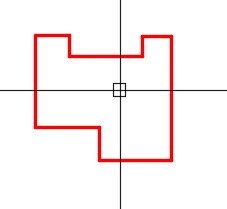
Crosshairs in The Normal Position Rotated 0 degrees
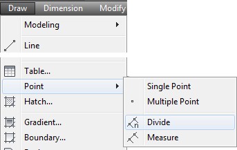
The DIVIDE Command
The DIVIDE command is used to divide a drawing object by inserting points on the object at calculated XY locations. It does not change the object in any way, it simply inserts points on it. It is important that the current layer is set to layer Construction when the DIVIDE command is used. That way, the points can be easily isolated from the object it is dividing. On lines and arcs, the DIVIDE command starts calculating from the endpoint of the selected object.
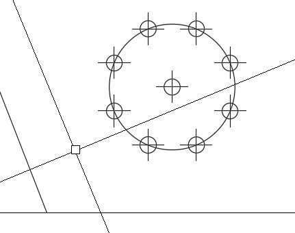
The DIVIDE command works different when dividing circles. Since a circle does not have an endpoint, the DIVIDE command will place the first point where the positive X axis of the crosshairs intersects the circle.
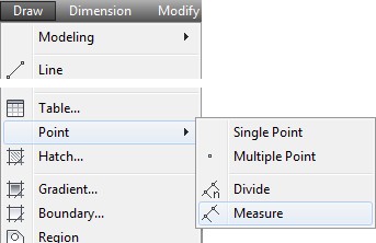
The MEASURE Command
The MEASURE command is used to divide a drawing object by inserting points on the object at specified distances along the object. It does not change the object in any way, it simply inserts points on it. It is important that the current layer is set to layer Construction when the MEASURE command is used. That way, the points can easily be isolated from the object being measured. The MEASURE command always starts the first measurement from the closest endpoint to the location where the object is selected.
The MEASURE command works different when measuring circles. Since a circle does not have an endpoint, the MEASURE command will start measuring at the point where the positive X axis of the crosshairs intersects the circle.
AutoCAD Command: ORTHO
The ORTHO command is used to lock the crosshairs to allow it to move only horizontal or vertical. When enabled, it applies to most commands. The current Ortho mode is displayed on the Status bar. The function F8 key toggles ortho mode off and on.
Shortcut: F8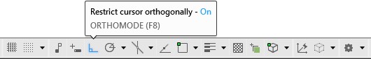
AutoCAD Command: DIVIDE
The DIVIDE command is used to insert points an equal distance apart by dividing the length of the drawing object selected by the number of divisions entered. The object being divided is not changed in any way by the command.
Shortcut: DIV
AutoCAD Command: MEASURE
The MEASURE command is used to insert points on a drawing object at a specified distance. The object being measured is not be changed in any way by the command.
Shortcut: ME
WORKALONG: Using the POINT, DIVIDE and MEASURE Commands
Step 1
Start a new drawing using the template: 2D English.
Step 2
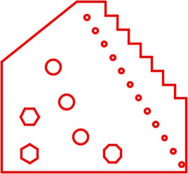
Save and name the drawing: AutoCAD 2D Workalong 17-1. (Figure Step 2)
Step 3
Create the layers: Object and Construction. Set layer: Construction as the current layer.
Step 4
Using what you learned earlier in the book, refer to Figure Step 2 and draw lines around the perimeter of the object. (Figure Step 4)
Step 5
From the Format Pull-down menu, select Point Style . This will open the Point Style dialogue box. Select the point style (center with black background) as shown in the figure. Set the Point Size to 3% and enable Set Size Relative to Screen. (Figure Step 5A and 5B)

Step 6
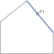
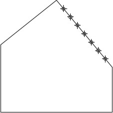
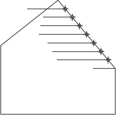
Enter the DIVIDE command, as shown below, and select the inclined line on the right. (Figure Step 6A and 6B)
Command: DIVIDE
Select object to divide: P1
Enter the number of segments or [Block]: 8
Command:
Step 7
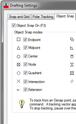
As taught earlier in the book, use the OSNAP command to open the Drafting Settings dialogue box. Enable the Node object snap mode. (Figure Step 7)
Step 8
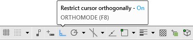
Press F8 to enable Ortho mode. Check to ensure that it is enabled by checking the Status bar. (Figure Step 8)
Step 9
Enable object snap and draw 8 horizontal lines by snapping to the points (nodes) as the first point of each line. The length of the lines is not important. (Figure Step 9)
Step 10
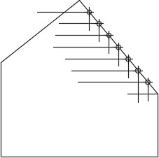
Draw 7 vertical lines by snapping to the points (nodes) as the first point of each line. The length of the lines is not important. Disable Ortho mode. (Figure Step 10)
Step 11
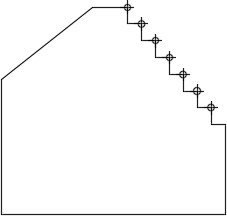
Trim the lines to form the steps as shown in the figure. (Figure Step 11)
Step 12
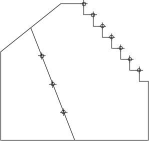
Draw a line by snapping to midpoint on the top left inclined line and the midpoint of the bottom line.
Step 13
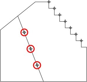
Using the DIVIDE command, divide the line into four segments. (Figure Step 13)
Step 14
Set layer: Object as the current layer. Enter the CIRCLE command and draw the three 0.40 diameter circles by snapping to the points (nodes) to locate the center of each circle. (Figure Step 14)
Step 15
Set layer: Construction as the current layer.
Step 16
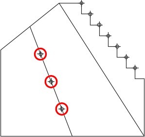
Draw a construction line from the top corner to the bottom corner as shown in the figure. Ensure that you snap to the endpoints of the lines. (Figure Step 16)
Step 17
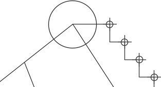
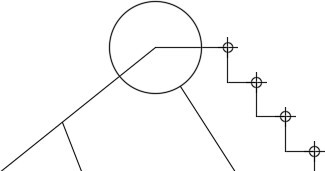
Draw a 0.5 radius construction circle with its center located at the top corner as shown in the figure. Trim the line. (Figure Step 17A and 17B)
Step 18
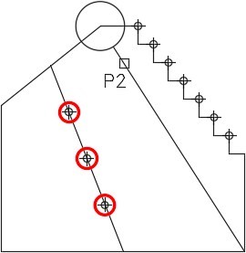
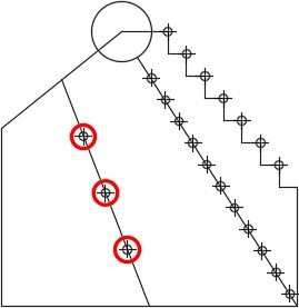
Enter the MEASURE command, as shown below, to insert points every 0.4325 units along the line. (Figure Step 18)
Command: MEASURE
Select object to measure: P2
Specify length of segment or [Block]: 0.4325
Command:
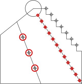
Step 19
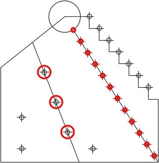
The drawing should now appear as shown in the figure. To demonstrate how the point size relative to the screen works, zoom in on your drawing until it fills the screen. Then execute the REGEN command. Notice how the point style size for the points changes. Zoom back out and execute the REGEN command again. (Figure Step 19)
Step 20
Set layer: Object as the current layer. Insert 12 – 0.125 diameter circles. One with its center located at the end of the line and the others with their centers located on the points that you inserted with the MEASURE command in Step 18. (Figure Step 20)
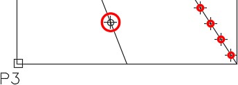
Step 21
Set layer: Construction as the current layer. Enter the ID command, as shown below, and snap to the endpoint of the bottom line to establish a reference point. (Figure Step 21)
Command: ID
Specify point: (end) P3
X = 1.7500 Y = 4.0000 Z = 0.0000
Command:
Step 22
Enter the POINT command, as shown below, to draw 3 points at the locations of the center of polygons. (Figure Step 22)
Command: POINT
Current point modes: PDMODE=34 PDSIZE=-3.0000 Specify a point: @.75,1.5
Command: POINT
Current point modes: PDMODE=34 PDSIZE=-3.0000 Specify a point: @0,-1
Command: POINT
Current point modes: PDMODE=34 PDSIZE=-3.0000
Specify a point: @2.25,0
Command:
Step 23
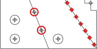
Draw three 0.5 diameter circles using the points as the location of the center of the circles. Ensure that you snap to the node when locating the center of each circle. (Figure Step 23)
Step 24
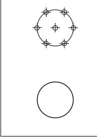
Using the DIVIDE command, divide the top left circle into 6 segments. (Figure Step 24)
Step 25
Enter the SNAPANG system variable as shown below to change the angle of the cursor to 90 degrees.
Command: SNAPANG
Enter new value for SNAPANG <0>: 90
Command:
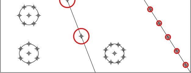
Step 26
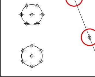
Enter the DIVIDE command and divide the bottom left circle into 6 segments. (Figure Step 26)
Step 27
Enter the system variable SNAPANG as shown below to change the angle of the crosshairs to 22.5 degrees.
Command: SNAPANG
Enter new value for SNAPANG <90>: 22.5
Command:
Step 28
Enter the DIVIDE command and divide the bottom right circle into 8 segments. (Figure Step 28A and 28B)
Step 29
Use the SNAPANG system variable, as shown below, to change the angle of the crosshairs to 0 degrees.
Command: SNAPANG
Enter new value for SNAPANG
<22.5>: 0
Command:
Step 30
On layer Object, draw the lines for the hexagons and the octagon by snapping from point to point (node to node) as shown in the figure. (Figure Step 30)
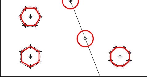
Step 31
Change the layer of any objects that you want to reside on layer Object. Freeze layer Construction. Your completed drawing should appear as shown in the figure. (Figure Step 31)
Step 32
Save and close the drawing.
Making Inquiries
The DIST and PROPERTIES commands are used to measure distances, find sizes, and locations of drawing objects. Before using these commands, it is important to understand the importance of the UNITS command.
Displaying Units
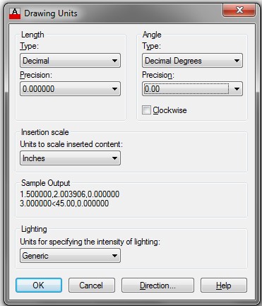
AutoCAD stores the drawing object’s properties and locations to a very high degree of accuracy. When the drawing object’s properties are displayed, either on the Command Line or in the Properties window, AutoCAD uses the setting in the Drawing Units dialogue box to display these properties rounded off as per the current settings. The answers are always displayed in drawing units but the precision and format of the answers is controlled by the settings in the Drawing Units dialogue box.
AutoCAD Command: UNITS
The UNITS command is used to open the Drawing Units dialogue box. It is used to set the way AutoCAD displays inquiries or drawing object properties.
Shortcut: UN
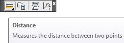
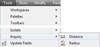
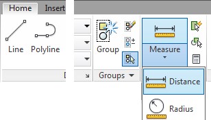
AutoCAD Command: DIST
The DIST command is used to measure distances between two XY coordinate locations.
Shortcut: DI
Geometry Lesson: Finding the Shortest Distance Between the Circumference of Two Circles
To find the shortest distance between the circumference of two circles, draw a construction line from the center of one circle to the center of the other as shown in Step 1. Measure the distance between the intersections of the lines and circles as shown in Step 2. If the line is trimmed as shown in Step 3, the length of the line is the shortest distance between the circle’s circumference. See Figure 17-9.
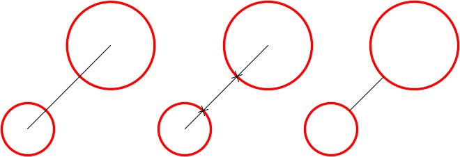
Figure 17-9
Finding the Shortest Distance Between the Circumference of two Circles
WORKALONG: Using Inquiry Commands
Step 1
Open the drawing: AutoCAD 2D Workalong 17-1 . Using the SAVEAS command, save the drawing with the name: AutoCAD 2D Workalong 17-2. (Figure Step 1)
Step 2
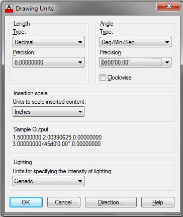
Enter the UNITS command. It will open the Drawing Units dialogue box. Set the dialogue box to match the figure. (Figure Step 2)
Step 3
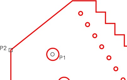
Enter the DIST command, as shown below, to measure the distance between the center of the circle and the end of the line as shown in the figure. Ensure that you snap to the center of the circle and the endpoint of the line. (Figure Step 3)
Command: DIST
Specify first point: (cen) P1
Specify second point: (end) P2
Command:
Step 4
Press F2 to open the Text window. The answer to the DIST command will display as shown in the figure. (Figure Step 4)
Step 5
Press F2 to close the Text window.
Step 6
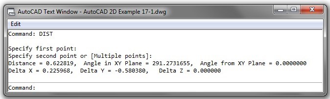
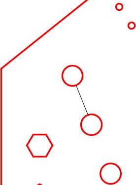
Draw a construction line from the center of circle to center of circle as shown in the figure. Ensure that you snap to the centers of the circle at both ends. Enter the DIST command as shown below to measure the shortest distance between circumferences of the circles by snapping to intersection of the construction line and the circles. (Figure Step 6)
Command: DIST
Specify first point: (int) P3
Specify second point: (int) P4
Command:
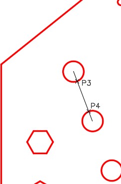
Step 7
Press F2 to open the Text window. The answer to the DIST command will display as shown in the figure. (Figure Step 7)
Step 8
Trim the construction line as shown in the figure. (Figure Step 8)
Step 9
Open the Properties window. Without entering a command, select the line. The Properties window will display the length of the line. (Figure Step 9)
Step 10
Set the Drawing Units dialogue box, as shown in the figure. (Figure Step 10)
Step 11
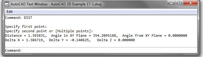
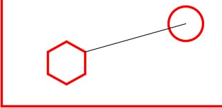
Draw a line from the center of the circle to the vertex on the hexagon as shown in the figure. (Figure Step 11)
Step 12
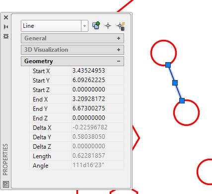
After trimming the line, select it. Check its length and angle in the Properties window. (Figure Step 12)
Step 13
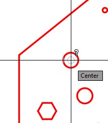
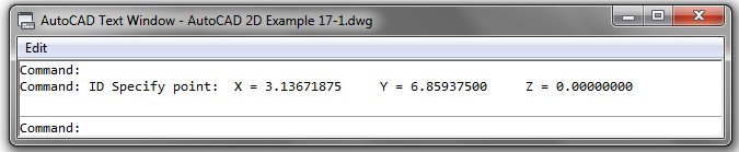
Turn layer: Construction off. Enter the ID command and snap to the center of the circle. Press F2 to open the Text window. (Figure Step 13A and 13B)
Step 14
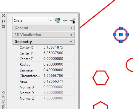
Select the circle as shown in the figure. Take note that the Properties window displays the XY center location plus the radius, diameter, circumference, and area of the circle. (Figure Step 14)
Step 15
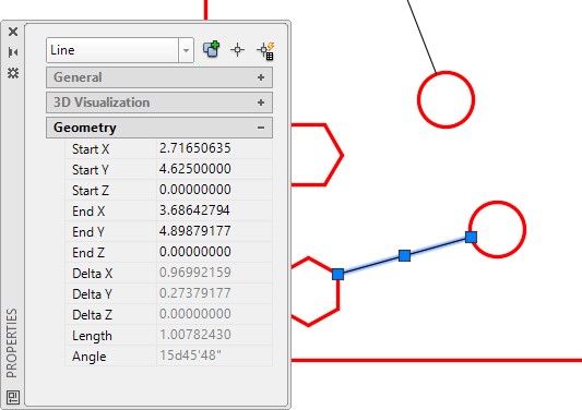
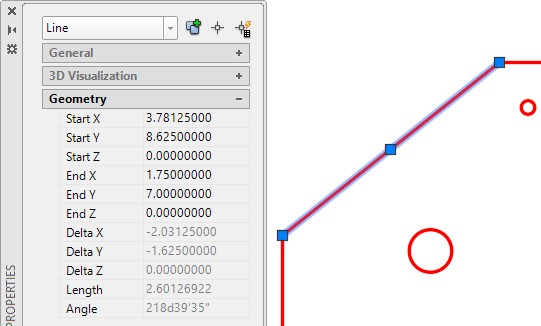
With the Properties window open, select the line as shown in the figure. Figure Step 15)
Step 16
Save and close the drawing.
Geometry Lesson: Finding the Centroid of any Triangle
To find the centroid (geometrical center) of any triangle, draw construction lines from each vertex to the midpoint of the opposite line of the triangle. The centroid of the triangle is the intersection of the three lines. See Figure 17-9.
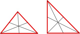
Finding the Center of a Triangle
Key Principles
Key Principles in Module 17
- A point is an AutoCAD drawing object that is one pixel in size.
- A node is the object snap mode for a point.
- AutoCAD stores the accuracy of the drawing object’s properties and locations to a very high degree. The UNITS command is used open the Drawing Units dialogue box where the you can set the format of how AutoCAD displays these properties and locations.
- The DIVIDE command insert points on the object by dividing the object’s length or perimeter into an equal number of segments specified by the user.
- The MEASURE command inserts points on an object at a user specified distance.
Lab Exercise 17-1
Time allowed: 45 minutes.
| Drawing Name | Template | Units |
|---|---|---|
| AutoCAD 2D Lab 17-1 | 2D Metric | Millimeters |
| Layer Name | Objects on Layer | Color |
|---|---|---|
| Construction | Construction objects | 253 |
| Object | All objects | Red |
Step 1
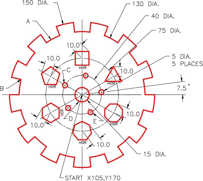
Draw the object shown in the figure using the layering scheme. (Figure Step 1A and 1B)

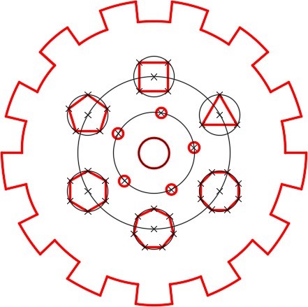
Completed Drawing
Step 2
Set the insertion units and check your drawing with the key.
Step 3
Turn layer: Key off and freeze layer: Construction.
Step 4
Using either the DIST command or the Properties window, find the following answers with the precision of 8 decimal places:
- Length of arc A: ______________________
- Distance from the center of circle C to center of circle E. ______________________
- Shortest distance from corner B to the circumference of circle C. ______________________
- The circumference of circle D: ______________________
(Check your answers on the key)
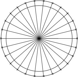
Hint 1
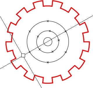
Using the DIVIDE command, divide the large circle into 26. (Figure Hint 1)
Hint 2
Rotate the cursor 7.5 degrees and divide the 40 diameter circle into 5. (Figure Hint 2)
Hint 3
Rotate the cursor 30 degrees and divide the 75 diameter circle into 6. (Figure Hint 3)
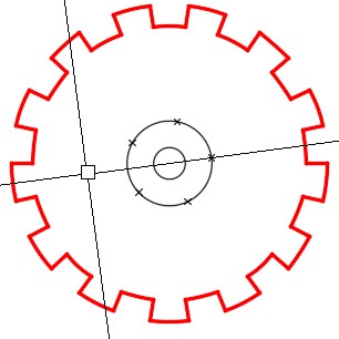
Hint 4
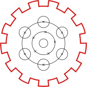
Draw 6 – 20 diameter circles locating their centers on the points. (Figure Hint 4)
Hint 5
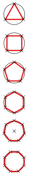
To draw the polygons, rotate the cursor to the appropriate angle as shown in the list below. (Figure Hint 5A and 5B)
Triangle = 90 degrees
Square = 45 degrees
Pentagon = 90 degrees
Hexagon = 90 degrees
Heptagon = 90 degrees
Octagon = 22.5 degrees
Lab Exercise 17-2
Time allowed: 50 minutes.
| Drawing Name | Template | Units |
|---|---|---|
| AutoCAD 2D Lab 17-2 | 2D English | Inches |
| Layer Name | Objects on Layer | Color |
|---|---|---|
| Construction | Construction objects | 253 |
| Object | All objects | Red |
Step 1
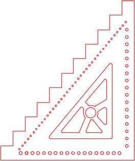
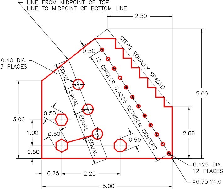
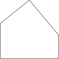
Draw the object shown in the figure using the layering scheme. (Figure Step 1A and 1B)
Step 2
Set the insertion units and check your drawing with the key.
Step 3
Turn layer: Key off and freeze layer: Construction.
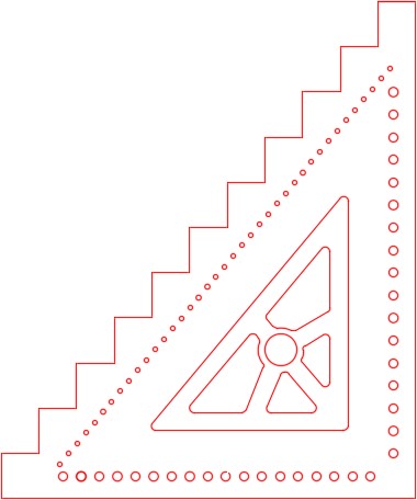
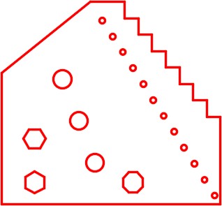
Completed Drawing
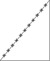
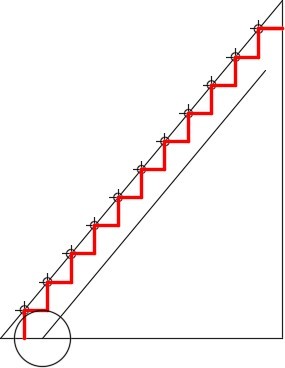
Hint 1
Using the DIVIDE command, divide the inclined line into 12. (Figure Hint 1)
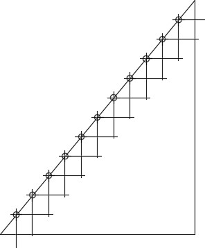
Hint 2
Construct the steps using ortho mode. (Figure Hint 2)
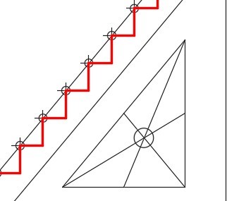
Hint 3
Trim the steps and change the layer they reside on to layer: Object. Offset the inclined line and draw a circle to measure the distance along the inclined line. (Figure Hint 3)
Hint 4
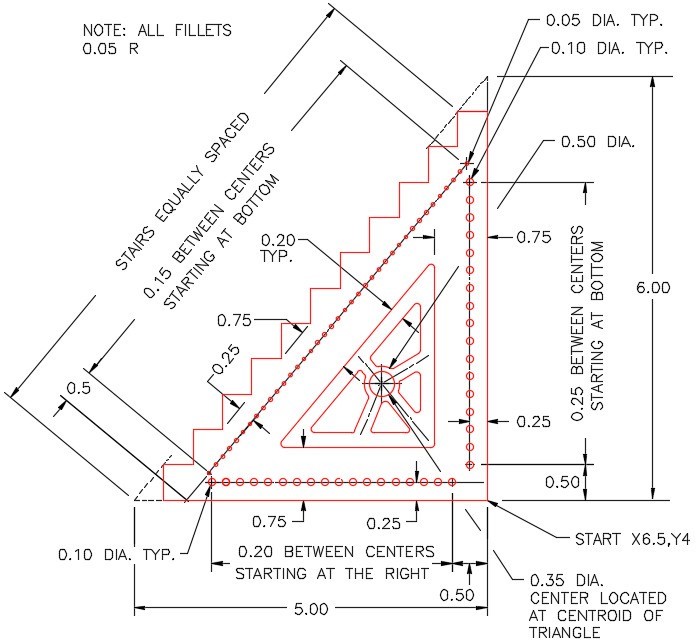
Draw the triangle by offsetting the three outsides 0.75 inches as shown in the dimensioned drawing. Using the Geometry Lesson: Finding the Centroid of any Triangle, find the centroid of the triangle and draw a 0.35 diameter circle using the intersection of the lines to locate its center. (Figure Hint 4)
Hint 5
Offset the outside lines of the triangle 0.20 inches towards the center. (Figure Hint 5)
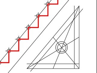
Hint 6
Offset the inside lines 0.10 inches on each side. (Figure Hint 6)
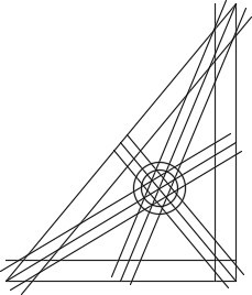
Hint 7
Trim all lines and the circle. Fillet all corners using a radius of 0.05 inches. The fillets should always be inserted last. (Figure Hint 7)
Hint 8
Change the layer of all objects to layer: Object. (Figure Hint 8)