Module 12: Fillets
Learning Outcomes
When you have completed this module, you will be able to:
- Describe tangency and explain how to locate the point of tengency.
- Describe a fillet.
- Apply the FILLET command to construct fillets between two drawing objects.
- Describe the object snap mode Tan.
- Apply the LINE command using the object snap mode Tan to draw lines tangent to arcs and circles.
Geometry Lesson: Tangency
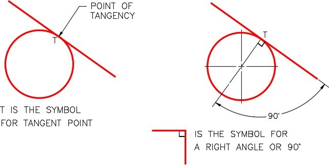
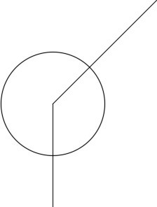
A point of tangency is the theoretical point where a line joins an arc, two arcs join each other, or two circles join each other making a smooth transition. A line is tangent to a circle or an arc when it passes touching only one point on the circle or arc. The tangent point is located where a line drawn perpendicular from the center of the circle or arc touches the line. Study Figure 12-1.
Tangency – Part 1
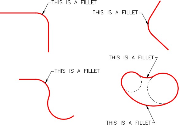
A fillet is a tangent arc. A tangent arc must be tangent at both ends where it connects to existing lines or arcs. Figure 12-2 shows five examples of fillets.
Tangency – Part 2
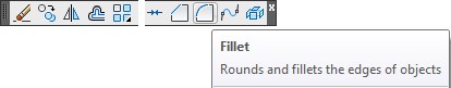
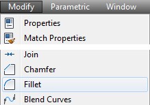
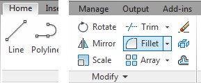
AutoCAD Command: FILLET
The FILLET command is used to draw a tangent arc. It inserts an arc tangent to the two existing
drawing objects selected in the command.
Shortcut: F
WORKALONG: Using the FILLET Command
Step 1
Start a new drawing using the template: 2D English.
Step 2
Save and name the drawing: AutoCAD 2D Workalong 12-1.
Step 3
Create layers: Object and Construction. Set layer: Object as the current layer.
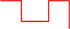
Step 4
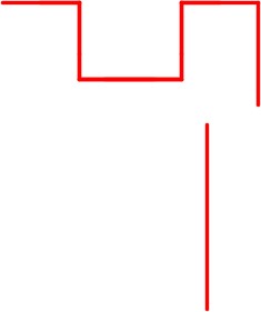
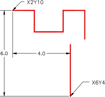
Using the LINE command and referring to the figures, draw the 6 lines to match the figure. (Figure Step 4A and 4B)
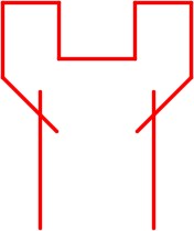
Step 5
Using the LINE command, draw the vertical line. (Figure Step 5A and 5B)
Step 6
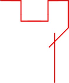
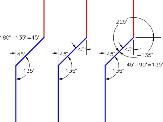
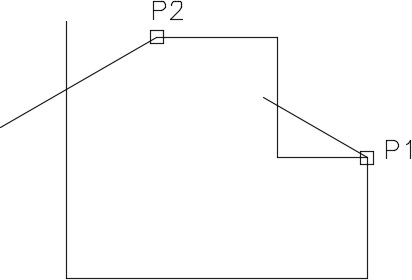
Using the LINE command, draw the inclined line. First you have to solve the angle. Guess at the length and try to make it longer. After you know the angle and the length, snap to end point of the existing to start the line. (Figure Step 6A and 6B)
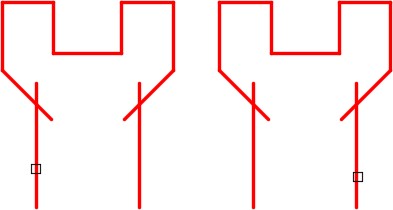
Step 7
Using the principles you just learned, use the LINE command to draw the two lines on the left side of the object. (Figure Step 7)
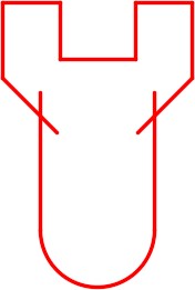
Step 8
Enter the FILLET command, as shown below, and select the two vertical lines to insert the fillet (tangent arc). (Figure Step 8A, 8B, and 8C)
Command: FILLET
Current settings: Mode = NOTRIM, Radius = 0.5000
Select first object or [Undo/Polyline/Radius/Trim/Multiple]: T
Enter Trim mode option [Trim/No trim] <No trim>: T
Select first object or [Undo/Polyline/Radius/Trim/Multiple]:
Command: (This commands simply sets the FILLET command to trim objects when filleted. You only have to do this the first time you use the FILLET command or if you re-set it to NOTRIM.)
Command: FILLET
Current settings: Mode = TRIM, Radius = 0.0000
Select first object or [Undo/Polyline/Radius/Trim/Multiple]: (Pick left vertical line)
Select first object or [Undo/Polyline/Radius/Trim/Multiple]: (Pick right vertical line)
Select second object or shift-select to apply corner:
Command:
Step 9
Enter the FILLET command, as shown below, to insert a 0.5 radius fillet between the two lines. (Figure Step 9A. 9B, and 9C)
Command: FILLET
Current settings: Mode = TRIM, Radius = 0.0000
Select first object or [Undo/Polyline/Radius/Trim/Multiple]: R
Specify fillet radius <0.0000>: 0.5 (Set the radius for the fillet.)
Select first object or [Undo/Polyline/Radius/Trim/Multiple]: (Pick right vertical line)
Select second object or shift-select to apply corner: (Pick the horizontal line)
Command:
Step 10
Using what you learned in Step 9, insert the 0.5 radius fillet on the other side to match the figure. (Figure Step 10)
Step 11
Using what you learned in Step 9 and 10, insert the two 0.75 radius fillets on top left and right corners. (Figure Step 11)
Step 12
Insert the four 1.0 radius fillets to match the figure. (Figure Step 12)
Step 13
Enter the CIRCLE command and draw 1.0 diameter circle by snapping to the center of the arc to locate the its center. The completed drawing should match the figure. (Figure Step 13A and 13B)
Step 14
Save and close the drawing.
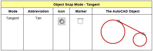
Object Snap Mode – Tangent
WORKALONG: Drawing Tangent Lines
Step 1
Start a new drawing using the template: 2D English.
Step 2
Save and name the drawing: AutoCAD 2D Workalong 12-2.
Step 3
Create the layers: Object and Construction. Set Layer: Construction as the current layer.
Step 4
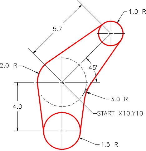
Referring to the figures, draw the 2 radius circle with its center at 10,10. (Figure Step 4A and 4B)
Step 5
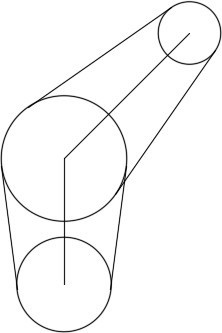
Using polar coordinates, enter the LINE command, two times, to draw two construction lines. Start each line starting at the center of the circle and ending at the center of the other two circles. (Figure Step 5)
Step 6
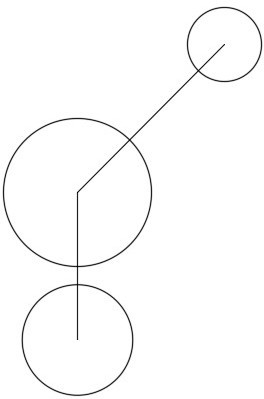
Draw circles locating their centers at the endpoints of the lines you drew in Step 5. (Figure Step 6)
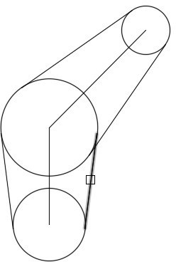
Step 7
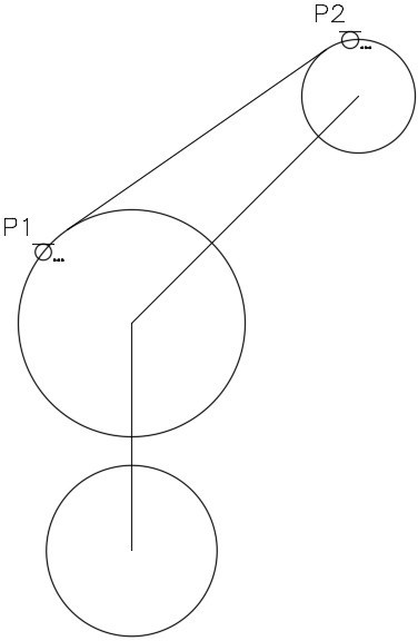
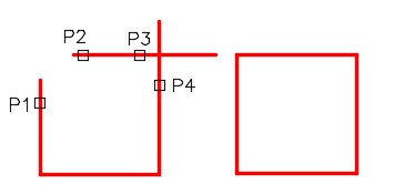
Enter the LINE command, as shown below, to draw a line tangent to the two circles. Enter the TAN object snap mode manually by typing it in on the keyboard. (Figure Step 7)
Command: LINE
Specify first point: TAN to P1
Specify next point or [Undo]: TAN to P2 Specify next point or [Undo]:
Command:
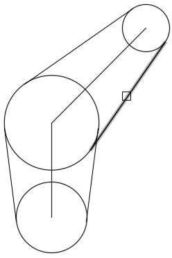
Step 8
Using what you learned in Step 7, enter the LINE command and draw a line tangent to the two circles as shown in the figure. (Figure Step 8)
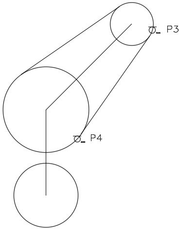
Command: LINE
Specify first point: TAN to P3
Specify next point or [Undo]: TAN to P4
Specify next point or [Undo]:
Command:
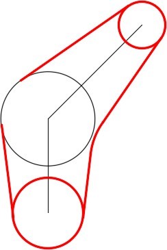
Step 9
Using what you just learned, insert the two tangent lines as shown in the figure. (Figure Step 9)
Step 10
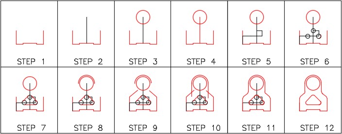
Using the FILLET command, insert a 3.0 radius fillet as shown in the figures. (Figure Step 10A , 10B, and 10C)

Step 11
Change the layer of the objects from layer: Construction to layer: Object to match the figure. (Figure Step 11)
Step 12
Freeze layer: Construction. (Figure Step 12)
Step 13
Insert a 2.0 radius fillet to complete the drawing. (Figure Step 13)
Step 14
Save and close the drawing.
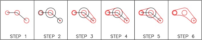
WORKALONG: Drawing Construction Techniques
Step 1
Start a new drawing using the template: 2D English.
Step 2
Save and name the drawing: AutoCAD 2D Workalong 12-3.
Step 3
Create layers: Object and Construction. Set layer: Construction as the current layer.
Step 4
Referring to the figures, enter the LINE command and draw the lines shown in the figures in two steps. (Figure 4A, 4B, and 4C)
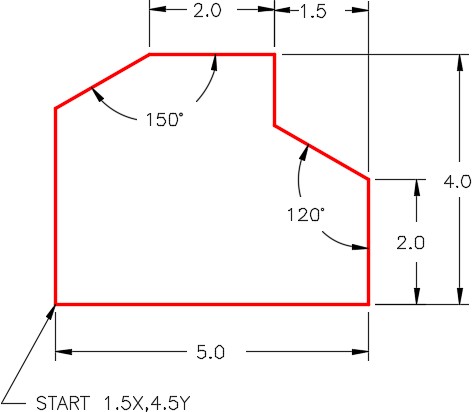
Step 5
Enter the LINE command, as shown below, to draw two lines. (Figure Step 5)
Command: L
Specify first point:<Osnap on> (end) P1
Specify next point or [Undo]: @2<150
(Since you don’t know the length of the line, draw a line of any length at the correct angle.)
Specify next point or [Undo]:
Command: L
Specify first point: (end) P2
Specify next point or [Undo]: @3<210
(Draw any length line at the correct angle.)
Specify next point or [Undo]:
Command:
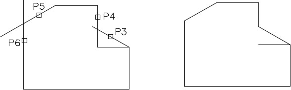
Step 6
Enter the FILLET as shown below. Set the radius to 0 to create perfect corners. (Figure Step 6A and 6B)
Command: FILLET
Current settings: Mode = TRIM, Radius = 0.3500
Select first object or [Undo/Polyline/Radius/Trim/Multiple]: R
Specify fillet radius <0.3500>: 0
(Set the radius to zero.)
Select first object or [Undo/Polyline/Radius/Trim/Multiple]: P3
Select second object or shift-select to apply corner: P4
Command: F
(F is the shortcut for the command FILLET.)
Current settings: Mode = TRIM, Radius = 0.0000
Select first object or [Undo/Polyline/Radius/Trim/Multiple]: P5
Select second object or shift-select to apply corner: P6
Command:
Step 7
Change the layer of the necessary lines to reside on layer: Object. Freeze layer: Construction. (Figure Step 7)
Step 8
Save and close the drawing.
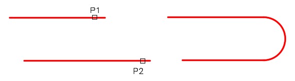
USER TIP: To insert an arc at the end of two parallel lines, use the FILLET command.Regardless of what radius is currently set in the FILLET command, AutoCAD will draw a tangent arc using the one-half distance between the lines as the radius. The lines do not have to be the same length.
Command: FILLET
Current settings: Mode = TRIM, Radius = 0.0
(Notice how the radius is set to zero. It can be any size.)
Select first object or [Polyline/Radius/Trim]: P1
(The first line you pick will retain it’s original length and the second one will be trimmed or extended.)
Select second object: P2
Command
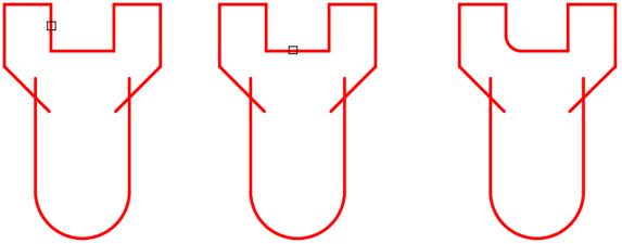
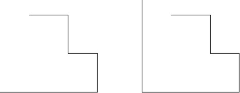
USER TIP: By setting the radius of the FILLET command to zero, the FILLET command will square the lines to make a perfect corner. The lines can be too short or too long or a combination of the two as shown in the figure on the right.
Key Principles
Key Principles in Module 12
- Point of tangency is the theoretical point where a line joins an arc, two arcs join each other, or two circles join each other making a smooth transition.
- A fillet is a tangent arc. To construct a fillet, use the FILLET command. The rule of thumb to follow is ‘ If the arc you are drawing is tangent to both objects it is connecting to, use the FILLET command. If the arc is tangent to one or neither of the objects, use the ARC command ‘.
- Use the LINE command and the TAN object snap mode to draw lines tangent to two circles or arcs. Make sure that you apply it to both ends of the line.
- By setting the radius of the FILLET command to zero, the FILLET command will square two lines to make a perfect corner.
Lab Exercise 12-1
Time allowed: 30 minutes.
| Drawing Name | Template | Units |
|---|---|---|
| AutoCAD 2D Lab 12-1 | 2D English | Inches |
| Layer Name | Objects on Layer | Color |
|---|---|---|
| Construction | Construction objects | 253 |
| Object | Lines, circle and arcs | Red |
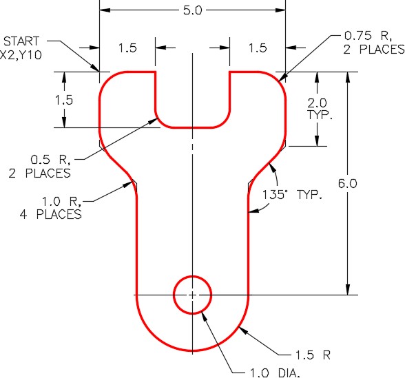
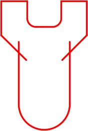
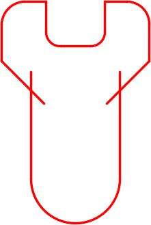
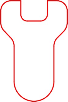
Step 1
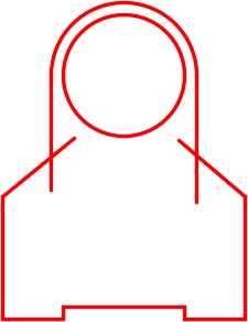
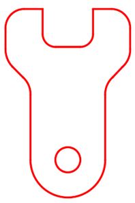
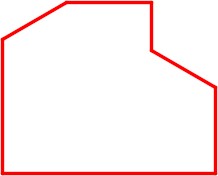
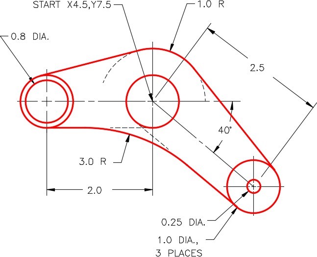
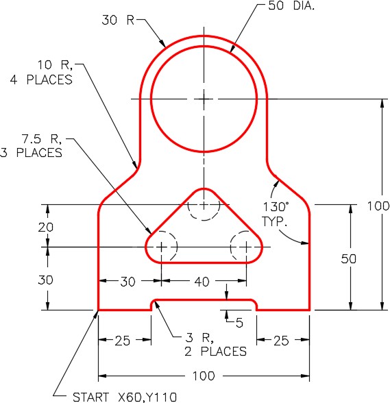
Draw the object shown in the figures using the layering scheme. (Figure Step 1A and 1B)
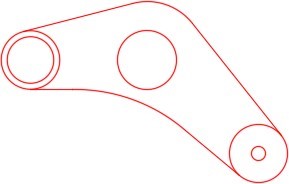
Completed Drawing
Step 2
Set the insertion units and check your drawing with the key.
Step 3
Turn layer: Key off and freeze layer: Construction.
Step 4
Save and close the drawing.
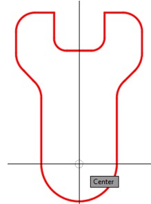
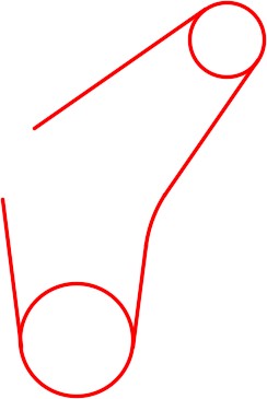
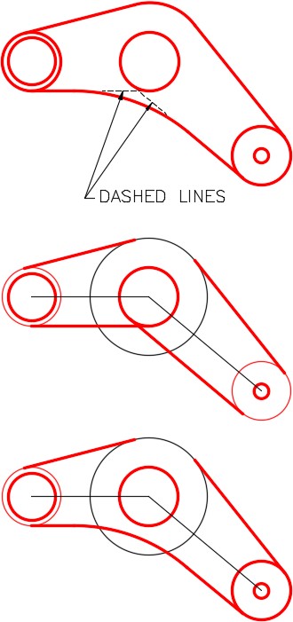
Hint 1
The dashed line shown in the dimensioned drawing indicates that the lines should be constructed tangent to the small circle from the circles on either end of the object. After the lines are inserted tangent to both circles, you can then insert the fillet. (Figure Hint 1)
Lab Exercise 12-2
Time allowed: 30 minutes.
| Drawing Name | Template | Units |
|---|---|---|
| AutoCAD 2D Lab 12-2 | 2D Metric | Millimeters |
| Layer Name | Objects on Layer | Color |
|---|---|---|
| Construction | Construction objects | 253 |
| Object | Lines, circles and arcs | Red |
Step 1
Draw the object shown in the dimensioned drawing using the layering scheme. (Figure Step 1A and 1B)
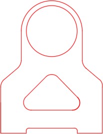
Completed Drawing
Step 2
Set the insertion units and check your drawing with the key.
Step 3
Turn layer: Key off and freeze layer: Construction.
Step 4
Save and close the drawing.
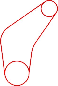
Hint 1
Draw a construction line from the midpoint of the line across the bottom of the slot 95 units in the positive Y direction. Draw a circle with its center at the end of the line. (Figure Hint 1)
Hint 2
Since you don’t know the exact length of the lines shown in the figure, draw them any length but in the correct direction. When you insert the fillets, the line will automatically be trimmed. (Figure Hint 2)