Module 4: Drawing Lines Using Cartesian Coordinates
Learning Outcomes
When you have completed this module, you will be able to:
- Describe the geometry of points and lines.
- Describe the Cartesian Coordinate System.
- Define and explain the terms lastpoint, absolute coordinates, and relative coordinates.
- Apply the LINE command to draw lines using the XY Cartesian Coordinate System using both absolute and relative coordinates.
Geometry Lesson: Points and Lines
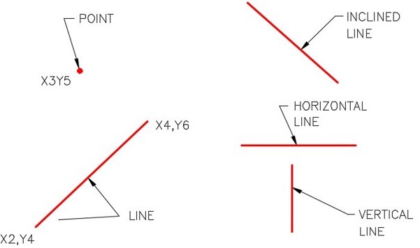
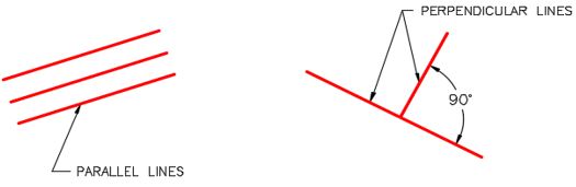
A point is defined as a single XY coordinate. It does not have a width, height, or depth. A line is the shortest distance between two XY coordinates. Lines can be horizontal, vertical, or inclined. Lines that are the same distance apart are called parallel lines. Perpendicular lines are at right angles to each other or 90 degrees apart. See Figure 4-1 and 4-2.
The Cartesian Coordinate System
To accurately draw an AutoCAD two dimensional (2D) drawing, you must enter XY coordinate locations. These XY coordinates are based on the Cartesian Coordinate System.
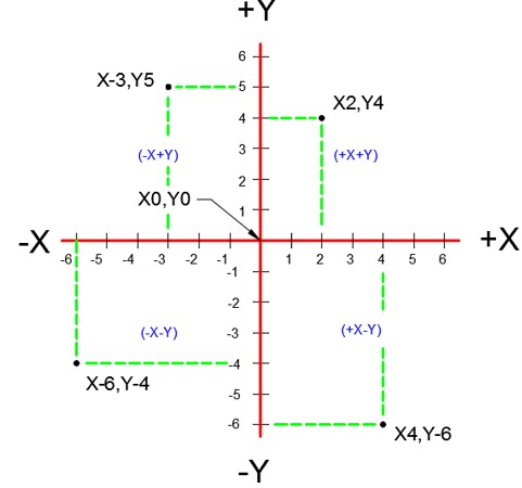
The Cartesian Coordinate System consists of two numbered lines crossing perpendicular to one another at their zero values. The horizontal axis is the X axis and the vertical axis is the Y axis. See Figure 4-3. A coordinate value is assigned to each location on the current construction plane. Throughout the AutoCAD 2D book you will be working on the same construction plane. Construction planes are fully explained in the AutoCAD 3D book.
When you are using a AutoCAD 2D command, each coordinate value consists of a pair of numbers, the first is the X coordinate and the second is the Y coordinate, written X,Y. The X and Y values must be separated by a comma. For example, X2,Y4 (entered in AutoCAD as 2,4) is the location 2 units to the right (positive) and 4 units up (positive) from X0,Y0 or 0,0.
The values can be either positive or negative. Positive numbers are default so the plus sign is not required. If the value is negative, the minus sign must precede the number. For example if entered in a an AutoCAD command, -3,5 is X minus 3 and Y positive 5.
Cartesian coordinates can be entered in a AutoCAD command as either absolute coordinates or relative coordinates.
Absolute Cartesian Coordinates
Absolute Cartesian Coordinates are always referenced to the absolute origin 0,0. The Absolute Cartesian Coordinate 3,4 (X3Y4) is 3 units to the right and 4 units upwards from 0,0 (X0Y0).
Negative values can also be used. The Absolute Cartesian Coordinate -4,2 (X-4,Y2) is 4 units to the left and 2 units upwards from 0,0 (X0Y0).
Relative Cartesian Coordinates
Relative Cartesian Coordinates are incremental to the lastpoint. To indicate to AutoCAD that the coordinate being entered is relative, the @ symbol must precede the coordinate value. For example, @2,6, which means ‘ from the lastpoint go 2 units in the positive X and 6 units in the positive Y ‘. Another example using negative values @4,-2 which means ‘ from the lastpoint go 4 units in the positive X and 2 units in the negative Y.
Lastpoint
The lastpoint is the last XY location that was used in an AutoCAD command. The lastpoint is very important to you when drawing in AutoCAD. AutoCAD remembers the lastpoint entered and saves it in the @ symbol. The @ symbol means ‘ The last absolute coordinate location ‘.
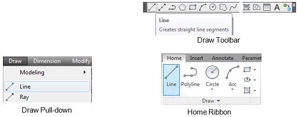
AutoCAD Command: LINE
The LINE command is used to draw lines.
Shortcut: L
WORKALONG: Drawing Lines Using Cartesian Coordinates – Part 1
Step 1
Using the NEW command, start a new drawing using the template: 2D English.
Step 2
Save and name the drawing: AutoCAD 2D Workalong 04-1. Save it in the folder: CAD Courses/AutoCAD 2D/Lab Exercises
Step 3
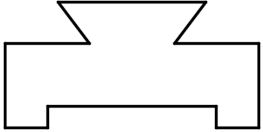
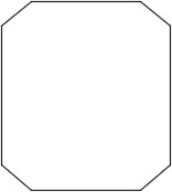
Enter the LINE command, as shown below, to draw the object shown in the figure. Keep in mind that you enter what is in bold font, the author’s comments are in italics, and everything else are AutoCAD responses or prompts. (Figure Step 3)
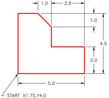
Command: LINE
Specify first point: 1.75,4
(Always start with an absolute coordinate. It must be a X then a Y separated with a comma.)
Specify next point or [Undo]: @5,0
(Then change to relative coordinates. Note the @ first, then X and Y.)
Specify next point or [Undo]: @0,2
Specify next point or [Close/Undo]: @-2.5,0
(A negative coordinate is used since the line is going in the negative X direction.)
Specify next point or [Close/Undo]: @0,1.5
Specify next point or [Close/Undo]: @-1,1
(When both the X and Y coordinates have a value other then zero, the line will be inclined.)
Specify next point or [Close/Undo]: @-1.5,0
Specify next point or [Close/Undo]: C
(You can use a C or 1.75,4 to close the last line and return to the first point.)
Command:
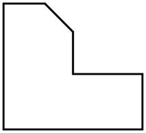
Step 4
Your completed drawing should match the figure. (Figure Step 4)
Step 5
Save and close the drawing.
MUST KNOW: When drawing inclined lines using Cartesian Coordinates, the value of both the X and the Y coordinates cannot be zero. See example below.
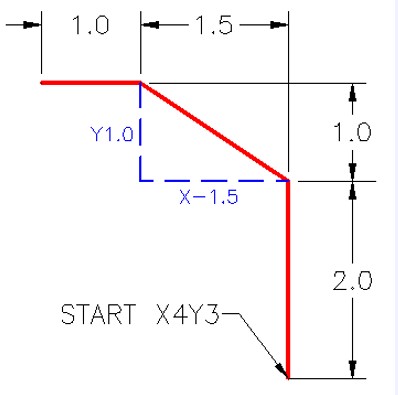
Command: LINE
Specify first point: 4,3
Specify next point or [Undo]: @0,2
Specify next point or [Undo]: @-1.5,1
Specify next point or [Close/Undo]: @-1,0
Specify next point or [Close/Undo]:
Command:
Note to draw the inclined line, you have to enter a X value and a Y value that is not zero. In this example, @-1.5,1 If either X or the Y is zero, then the line would be either horizontal or vertical. See Figure 4-4.
In Module 10, you will be taught how to draw incline lines using Polar Coordinates.
WORKALONG: Drawing Lines Using Cartesian Coordinates – Part 2
Step 1
Using the NEW command, start a new drawing using the template: 2D English.
Step 2
Save and name the drawing: AutoCAD 2D Workalong 04-2. Save it in the folder: CAD Courses/AutoCAD 2D/Lab Exercises
Step 3
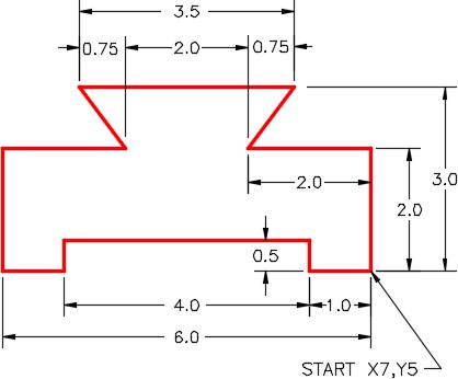
Enter the LINE command, as shown below, to draw the object shown in the figure. (Figure Step 3)
Command: L
(L is the shortcut for the LINE command)
Specify first point: 7,5
Specify next point or [Undo]: @0,2
Specify next point or [Undo]: @-2,0
Specify next point or [Close/Undo]: @.75,1
(You can draw an inclined line by entering a number other then zero for both the X and Y.)
Specify next point or [Close/Undo]: @-3.5,0
Specify next point or [Close/Undo]: @-.75,-1
Specify next point or [Close/Undo]: U
(When you make an input error, enter a U to go back one step. More than one U can be entered to step back further. Ensure that you press the ENTER or SPACE after each one.)
Specify next point or [Close/Undo]: @.75,-1
Specify next point or [Close/Undo]: @-2,0
Specify next point or [Close/Undo]: @0,-2
Specify next point or [Close/Undo]: @1,0
Specify next point or [Close/Undo]: @0,.5
Specify next point or [Close/Undo]: @4,0
Specify next point or [Close/Undo]: @0,-.5
Specify next point or [Close/Undo]: 7,5
(The object was closed by entering the absolute coordinate of the first point.)
Specify next point or [Close/Undo]: Command:
Step 4
Your completed object should match the figure. (Figure Step 4)
Step 5
Save and close the drawing.
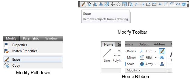
Deleting Objects
To delete existing drawing objects, you can either use the ERASE command or the Delete key.
Using the ERASE Command
When deleting drawing objects using the ERASE command, the drawing objects can either be selected before or after the command is entered. If the command is entered before selecting the objects, select the objects when prompted by the ‘ Select Object ‘ prompt, as shown below. If the objects are selected before entering the ERASE command, there is no prompt.
Command: ERASE
Select Object:
Command:
Using the Delete Key
When deleting objects using the Delete key, select the object or objects before pressing the key.
AutoCAD Command: ERASE
The ERASE command is used to permanently remove drawing objects from the drawing.
Shortcut: E
WORKALONG: Deleting Drawing Objects
Step 1
Open the drawing: AutoCAD 2D Workalong 04-1.
Step 2
Using the SAVEAS command, save the drawing with the name: AutoCAD 2D Workalong 04-3. (Figure Step 2)
Step 3
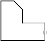
Enter the ERASE command as shown below. Move the pickbox onto the horizontal line and select it by pressing the left mouse button. Move the cursor onto the vertical line and select it. Press the Enter key to execute the command. (Figure Step 3A, 3B, and 3C)
Command: ERASE
Select objects: 1 found
Select objects: 1 found, 2 total Select objects:
Command:
Step 4
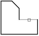
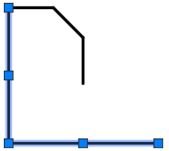
To delete drawing objects without entering a command, move the pickbox onto the lines,
as shown in the figure, and select them by clicking the left mouse button. They will highlight and appear dashed with small blue squares on them. When the lines display as shown in the figure, press the Delete key on the keyboard. (Figure Step 4A and 4B)
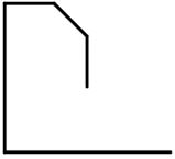
Completed Drawing
Step 5
Save and close the drawing.
Key Principles
Key Principles in Module 4
- The Cartesian Coordinate System consists of two numbered lines crossing perpendicular to one another at their zero values. The horizontal axis is the X axis and the vertical axis is the Y axis.
- Absolute Cartesian Coordinates are always referenced to the absolute origin 0,0.
- The @ symbol means ‘ The last absolute coordinate location ‘ or sometimes called the lastpoint. Relative Cartesian Coordinates must be preceded with @ symbol.
- To close the last line of a series of lines, enter either ‘ C ‘ (Close) or the absolute coordinate of the first point.
- To delete existing drawing objects, you can either use the ERASE command or the Delete key.
- Objects can either be selected before or after a command is entered.
- To unselect a selected drawing object, press the Esc key. Sometimes it has to be pressed twice.
Lab Exercise 4-1
Time allowed: 30 minutes.
| Drawing Name | Template | Units |
|---|---|---|
| AutoCAD 2D Lab 04-1 | 2D English | Inches |
Step 1
Start a new drawing using the template shown above.
Step 2
Save and name the drawing: AutoCAD 2D Lab 04-1 in the folder: CAD Courses/AutoCAD 2D/Lab Exercises.
Step 3
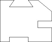
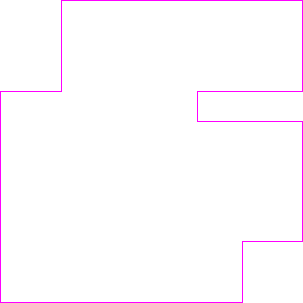
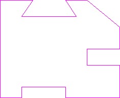
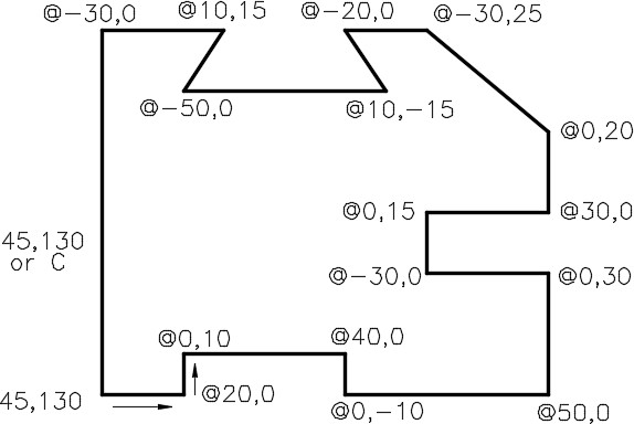
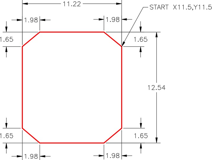
Using the LINE command, draw the object shown in the figure. (Figure Step 3A and 3B)
Completed Drawing
Step 4
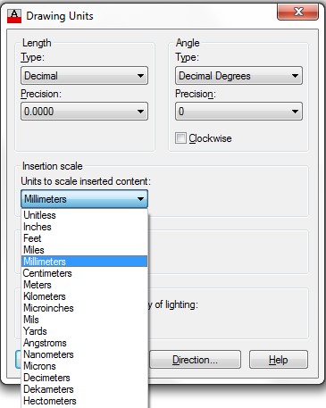
Enter the UNITS command. In the Drawing Units dialogue box, set the Insertion Units to Inches. (Figure Step 4)
Step 5
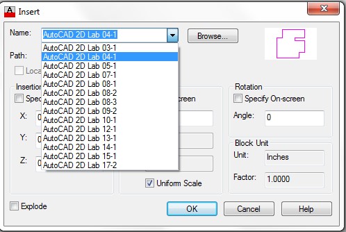
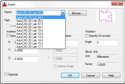
Check your drawing with the key. The key name is the same as the drawing name. (Figure Step 5)
Step 6
Your drawing should match the figure. (Figure Step 6)
Step 7
Save and close the drawing.
Hint 1
See Figure Hint 1.

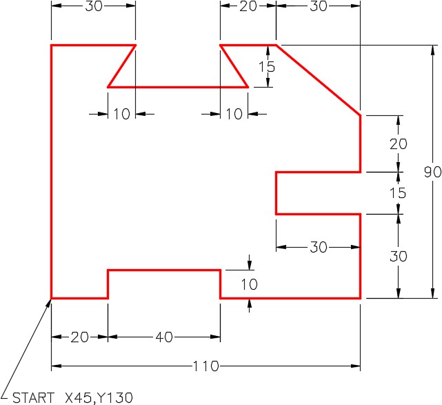
Lab Exercise 4-2
Time allowed: 30 minutes.
| Drawing Name | Template | Units |
|---|---|---|
| AutoCAD 2D Lab 04-2 | 2D Metric | Millimeters |
Step 1
Start a new drawing using the template shown above.
Step 2
Save and name the drawing: AutoCAD 2D Lab 04-2 in the folder: CAD Courses/AutoCAD 2D/Lab Exercises.
Step 3
Using the LINE command, draw the object shown in the figure. (Figure Step 3A and 3B)

Completed Drawing

Step 4
Enter the UNITS command. In the Drawing Units dialogue box, set the Insertion Units to Millimeters. (Figure Step 4)

Step 5
Check your drawing with the key. The key name is the same as the drawing name. (Figure Step 5)
Step 6
Your drawing should match the figure. (Figure Step 6)
Step 7
Save and close the drawing.
Hint 1
See Figure Hint 1.
Lab Exercise 4-3
Time allowed: 30 minutes.
| Drawing Name | Template | Units |
|---|---|---|
| AutoCAD 2D Lab 04-3 | 2D English | Inches |
Step 1
Start a new drawing using the template shown above.
Step 2
Save and name the drawing: AutoCAD 2D Lab 04-3 in the folder: CAD Courses/AutoCAD 2D/Lab Exercises.
Step 3
Using the LINE command, draw the object shown in the figure. (Figure Step 3A and 3B)
Completed Drawing
Step 4
Enter the UNITS command. In the Drawing Units dialogue box, set the Insertion Units to Inches.
Step 5
Check your drawing with the key.
Step 6
Save and close the drawing.
