Module 9: Controlling the Drawing
Learning Outcomes
When you have completed this module, you will be able to:
- Describe the drawing terms; limits, extents, scale, units, and regeneration.
- Apply the ZOOM, PAN, REGEN, and VIEWRES commands and explain how you use them to control the drawing.
Controlling the Drawing
To control the drawing and improve your drawing speed, it is important for you to understand the drawing terms; limits, extents, scale, units, and regeneration and how they relate to the current drawing.
Drawing Limits
An AutoCAD drawing has an unlimited amount of model space available to draw in. The drawing limits are a user defined rectangular or square shape of 2D model space. The size of the drawing limits can be changed, as required, at anytime.
Drawing limits were important before layouts were added to AutoCAD in AutoCAD 2000. They are not that important to AutoCAD 2000 and newer users but are still part of the software.
Drawing Extents
The drawing extents is defined as the smallest rectangle that will fit around all existing drawing objects in the current drawing that are visible (on a thawed layer). It is possible to draw outside the drawing limits and therefore objects that are outside the limits may not be visible in the normal drawing display. By being able to display the drawing extents, all visible (thawed) drawing objects that exist in the current drawing will display in the Graphic window. Being able to display the drawing extents is very important.
Since Model space is very large, objects are sometimes placed, by accident, somewhere out in space. If this happens in a drawing, it can severely derogate the performance of the drawing. Sometimes the only way to work on a drawing that is derogated is to find the erroneous objects and delete them. They can easily be found by displaying the drawing extents.
Drawing Scale
The general rule for all AutoCAD drawings is to always draw the object at full scale or full size. Scaling is done in the viewports in the layouts. This is taught in Module 18.
Drawing Units
AutoCAD drawings are unitless. If a unit of 1 is entered into a drawing and the units selected by the creator for that drawing are inches, then 1 means 1 inch. From that point forward all units entered into that drawing must be entered as inches. In another drawing, the operator creating the drawing picks the units to be millimeters. All numbers entered in that drawing must be entered in millimeters.
To sum up, when a drawing is first started, the creator must make a decision as to what units will be used for that drawing. From that point on, all numbers entered into that drawing must be entered in those units.
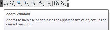
Zooming
Zooming is the process of moving the drawing objects closer or further away from your eyes without actually changing the size of the objects or their location in model or paper space. It is an important tool for you and is used extensively in the drawing process. Drawings can be very large and therefore you must be able to zoom in to be able to see in greater detail and zoom out again to work on the overall drawing.
The most efficient method to zoom a drawing is to locate the Graphic cursor in the center of the area to be zoom and then rotate the wheel on the mouse forward or backward. While the AutoCAD command ZOOM can be also used to zoom the drawing, using the wheel to zoom will greatly increase your drawing speed.
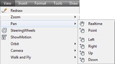
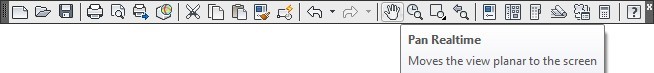
Panning
Panning is the process of moving the existing drawing objects around the Graphic window without actually physically moving any of the drawing object’s current location in model or paper space.
The most efficient method to pan a drawing is with the wheel on the mouse. Press and hold the wheel down and them move the mouse to pan the drawing. A Pan Hand cursor will replace the Graphic cursor when you hold the mouse wheel down. While the AutoCAD command PAN can be used to pan the drawing, using the wheel will greatly increase your drawing speed.
Regenerating the Drawing
AutoCAD stores all existing drawing objects and their properties in a database format in the .dwg file. When a drawing is opened, AutoCAD reads the .dwg file and constructs the drawing objects, one at time, displaying them in the Graphic window.
There are times when working on a drawing that it must be reconstructed from the .dwg file. This is called regeneration. The command used to do this is REGEN. There are many reasons for regeneration and they will become clear in future modules. Since some commands do not automatically regenerate, it is up to you to manually execute the REGEN command to force the display of any changes that happened when those commands was executed.
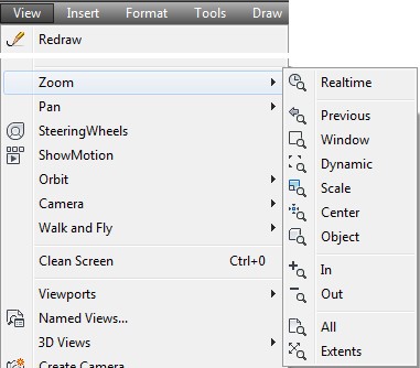
AutoCAD Command: ZOOM
The ZOOM command is used to move the existing drawing objects closer or farther away from the user’s eyes without changing the drawing object’s physical size.
Shortcut: Z
AutoCAD Command: PAN
The PAN command is used to move the drawing objects around the Graphic window without
physically moving them.
Shortcut: P
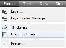
AutoCAD Command: LIMITS
The LIMITS command is used to set the drawing limits.
Shortcut: none
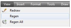
AutoCAD Command: REGEN
The REGEN command is used to reconstruct the drawing objects from the .dwg file and display them in the Graphic window.
Shortcut: RE
AutoCAD Command: VIEWRES
The VIEWRES command sets the number of vectors that AutoCAD uses when it displays circles
and arcs in the Graphic window.
Shortcut: none
WORKALONG: Using the LIMITS, ZOOM, PAN, REGEN, and VIEWRES Commands
Step 1
Open the drawing: AutoCAD 2D Workalong 08-1.
Step 2
Using the SAVEAS command, save the drawing with the name: AutoCAD 2D Workalong 09-1.
Step 3
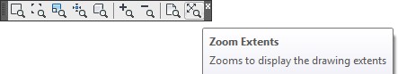
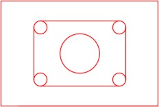
Enter the ZOOM Extents command, as shown below. The drawing should appear as shown in the figure. (Figure Step 3)
Command: ZOOM
Specify corner of window, enter a scale factor (nX or nXP), or
[All/Center/Dynamic/Extents/Previous/Scale/Window/Object] <real time>: E
Command:

Step 4
Practice zooming the drawing in and out by rotating the wheel on the mouse.
Step 5
Move the crosshairs to approximately the center of the object and push the middle wheel down and hold it. A Hand icon will replace the crosshairs. While holding the wheel down, pan the drawing around.
Step 6
Enter the ZOOM Extents command to zoom the drawing to its extents. Step 7 Enter the LIMITS command, as shown below, to set the drawing limits.
Command: LIMITS
Reset Model space limits:
Specify lower left corner or [ON/OFF] <0.0000,0.0000>:
Specify upper right corner <12.0000,9.0000>: 8.5,11
Command:
Step 8
Use the CIRCLE command, as shown below, to draw a 1 diameter circle with its center at X20,Y22.
Command: C
CIRCLE Specify center point for circle or [3P/2P/Ttr (tan tan radius)]: 20,22
Specify radius of circle or [Diameter]: D
Specify diameter of circle: 1
Command:
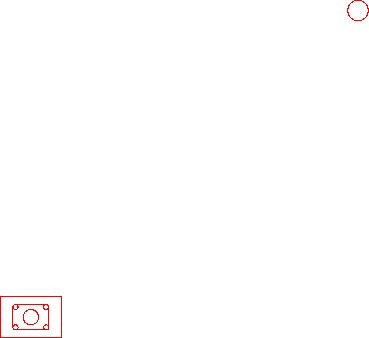
Step 9
Enter the ZOOM Extents command. Your drawing should appear as shown in the figure. (Figure Step 9)
Step 10
Use the CIRCLE command, as shown below, to draw a 1 diameter circle with its center at X-35,Y-35.
Command: C
CIRCLE Specify center point for circle or [3P/2P/Ttr (tan tan radius)]: -35,-35
Specify radius of circle or [Diameter]: D
Specify diameter of circle: 1
Command:
Step 11
Enter the ZOOM Extents command. Your drawing should appear as shown in the figure. (Figure Step 11)
Step 12
Delete the two circles that you inserted in Steps 8 and 10. Enter the ZOOM Extents command again. The drawing should match the figure. (Figure Step 12)
Step 13
Enter the VIEWRES and REGEN commands, as shown below. (Figure Step 13)
Command: VIEWRES
Do you want fast zooms? [Yes/No] <Y>: Y
Enter circle zoom percent (1-20000) <2000>: 20000
Command: REGEN
Regenerating model

Step 14
Save and close the drawing.
USER TIP: Since the ZOOM Extents command is used a lot during the drawing process, there is a shortcut to execute this command. Move the cursor to somewhere on the Graphic window and double click the wheel or middle button on the mouse.When attempting to find all the existing objects by displaying the drawing extents, ensure that all layers are thawed and on.
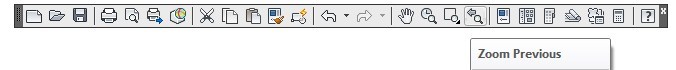
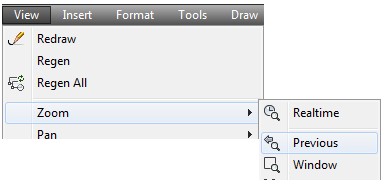
USER TIP: The ZOOM Previous command allows you to step back through the previous zoomed states. This allows you to quickly zoom in on an object, draw or edit, and then return back to the previous zoomed state.
Key Principles
Key Principles in Module 9
- The drawing extents is the smallest rectangle that will fit around all the existing drawing objects in the drawing.
- Always draw all objects in Model space at full size or full scale.
- AutoCAD drawings are unitless. The operator who creates the drawing makes the decision what units will be used for that drawing.
- When a drawing is regenerated, AutoCAD reconstructs the drawing from the .dwg file. Drawings regenerate when they are opened but you can force an open drawing to regenerate with the REGEN command.
Lab Exercise 9-1
Time allowed: 40 minutes.
| Drawing Name | Template | Units |
|---|---|---|
| AutoCAD 2D Lab 09-1 | 2D Metric | Millimeters |
| Layer Name | Objects on Layer | Color |
|---|---|---|
| Construction | Construction objects | 253 |
| Object | All objects | Red |
Step 1
Setup the layers using the Layering Scheme shown above.
Step 2
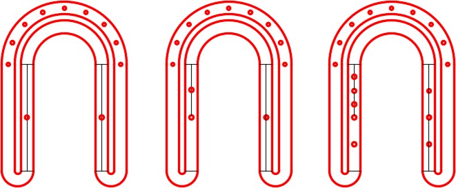
Draw the object shown in the figure using the layering scheme. (Figure Step 2A, 2B, and 2C)
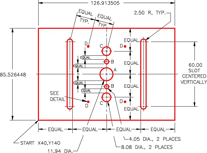
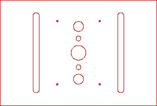
Completed Drawing
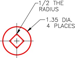
Detail
Step 3
Enter the UNITS command. In the Units dialogue box, set the Insertion Units to Millimeters.
Step 4
Check the drawing’s accuracy with the key.
Step 5
If there are any errors, turn layer Key off and correct the drawing.
Step 6
Turn layer: Key on. If the drawing still inaccurate, go back to Step 7.
Step 7
Turn layer: Key off.
Step 8
Save and close the drawing.
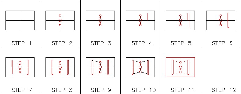
Hint 1
See the figures. (Figure Hint 1A and 1B)
Hint 2
Construction lines for circle B. (Figure Hint 2)
Hint 3
Construction to draw circle D. (Figure Hint 3)
Hint 4
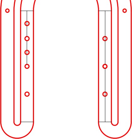
Construction objects in the drawing. (Figure Hint 4)
Construction Lines
Lab Exercise 9-2
Time allowed: 30 minutes.
| Drawing Name | Template | Units |
|---|---|---|
| AutoCAD 2D Lab 09-2 | 2D English | Inches |
| Layer Name | Objects on Layer | Color |
|---|---|---|
| Construction | Construction objects | 253 |
| Object | All objects | Red |
Step 1
Setup the layers using the Layering Scheme shown above.
Step 2
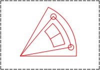
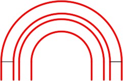
Draw the object shown in the figure using the layering scheme. (Figure Step 2A and 2B)
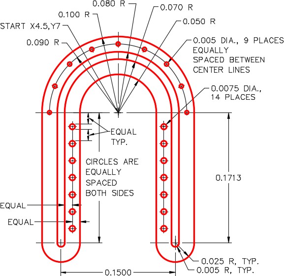
Completed Drawing
Step 3
Set the viewres to 10,000 and regenerate your drawing.
Step 4
Enter the UNITS command. In the Units dialogue box, set the Insertion Units to Inches.
Step 5
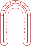
Check your drawing with the key. The key name is the same as the drawing name.
Step 6
If you have any errors, turn layer: Key off and correct your drawing.
Step 7
Turn layer: Key on to check your drawing. If it is still inaccurate, go back to Step 7.
Step 8
Turn layer: Key off and freeze layer: Construction.
Step 9
Save and close the drawing.
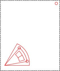
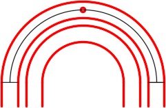
Hint 1
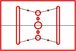
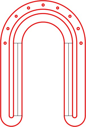
Draw two construction lines from end of arc to end of arc as shown in the figure. (Figure Hint 1)
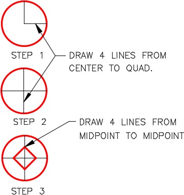
Hint 2
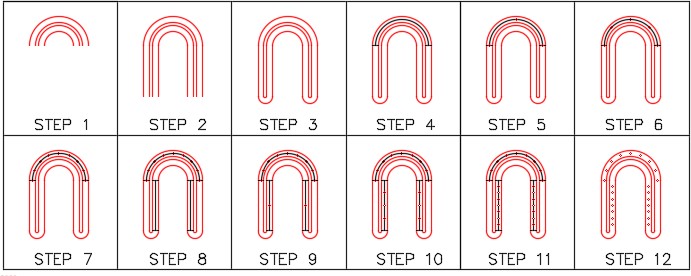
Draw two circles locating their centers at the midpoint of the construction lines that you drew in Hint Step 1. Construction an arc from center of the circle on the right side to the center of the circle on the left side. Draw a circle at the midpoint of the arc. (Figure Step Hint 2)
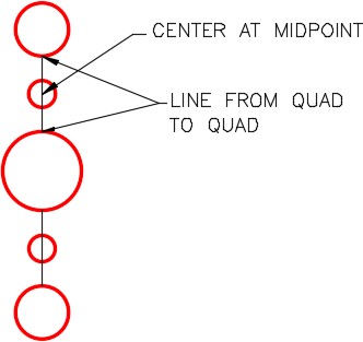
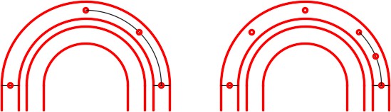
Hint 3
Erase the construction arc you drew in Hint Step 2. Draw a construction arc from the center of the circle to the center of the circle. Draw a circle at the midpoint of the arc. You will have to repeat this three more times. (Figure Hint 3A and 3B)
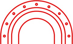
Hint 4
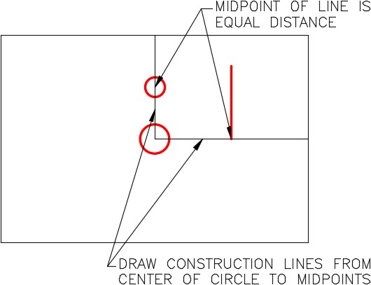
Insert four construction lines from the end of arc to the end of arc. Draw a construction line from the midpoint of line to midpoint of line on both sides. (Figure Hint 4)
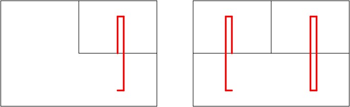
Hint 5
Draw a circle at the midpoint of the line on both sides. Erase the construction line and draw a new construction line from the quad of the circle to the midpoint of the line. It is important to draw from the quad to the midpoint. Insert a circle at the midpoint of the line. Erase the construction line and repeat as shown in the figures. (Figure Hint 5A and 5B)