Module 10: Drawing Lines Using Polar Coordinates
Learning Outcomes
When you have completed this module, you will be able to:
- Describe the geometry of angles.
- Describe the Polar Coordinate System.
- Apply the LINE command to draw lines using the Polar Coordinate System.
Geometry Lesson: Angles
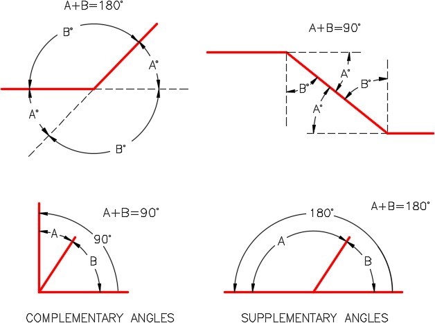
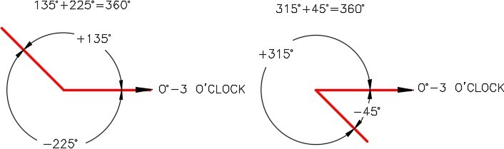
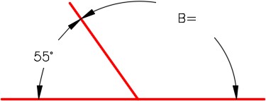
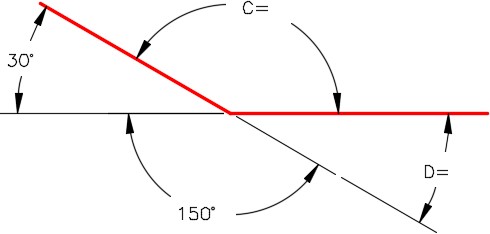
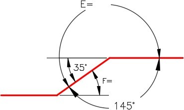
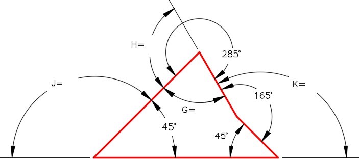
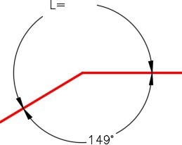
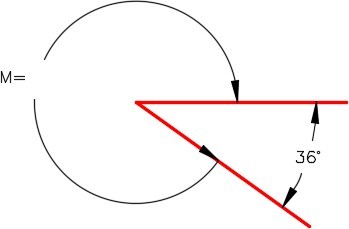
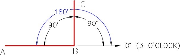
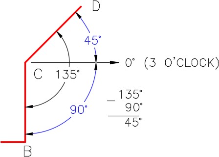
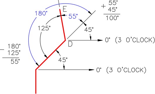
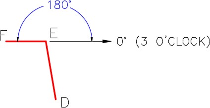
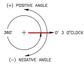
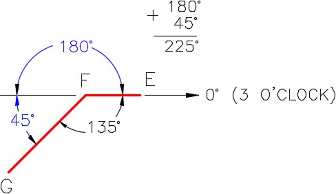
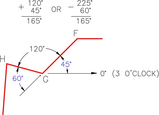
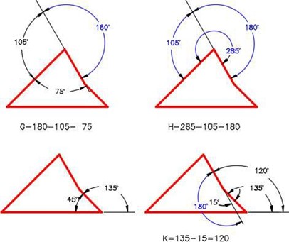
An angle is formed by two intersecting lines. When measuring an angle in a drawing, AutoCAD defines zero degrees at 3:00 o’clock with the positive angle in the counterclockwise direction and a negative angle in the clockwise direction. Study angle geometry in Figure 10-1, 10-2, and 10-3. These principles are used extensively to construct drawings in AutoCAD.
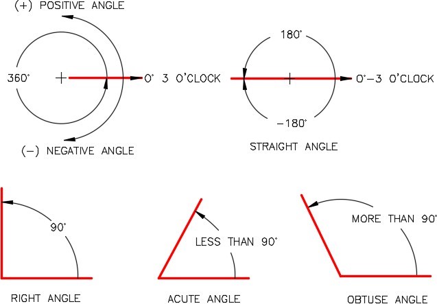
All angles are express in either positive or negative degrees. AutoCAD will accept either. Since positive is the default, the positive sign does not have to precede the number but a negative angle must be preceded by the negative sign.
WORKALONG: Working With Angles
Step 1
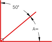
Study Figure 10-1, 10-2, and 10-3. Using what you learned and without drawing in AutoCAD, find the answers for the angles A to M. After you find a solution to all of the angles, check your answers with the solutions at the end of the module.
The Polar Coordinate System
The Polar Coordinate System is a two-dimensional coordinate system in which each point on a plane is determined by a distance from a reference point and an angle from a reference direction. In AutoCAD, you use it when you are given a distance and an angle from a known coordinate location. All angles are measured with 0 degrees at 3:00 o’clock. The angles are positive in the counterclockwise direction and negative in the clockwise direction. See Figure 10-4.
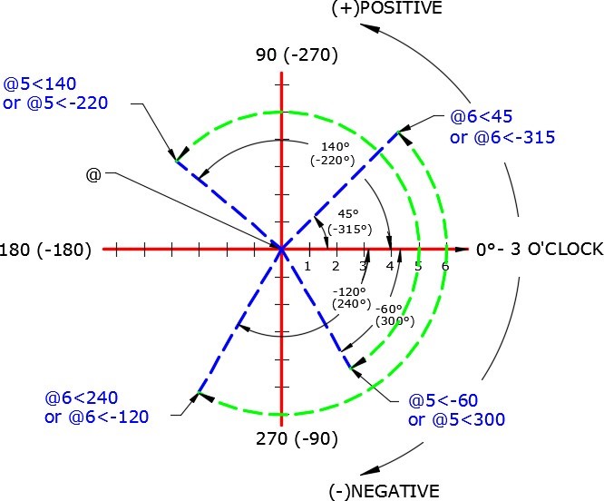
A polar coordinate is entered into AutoCAD as a distance, a less than symbol, and an angle. In all cases, the @ symbol must precede the distance. i.e.
@6<45
means ‘ from the last point, go 6 units at an angle of 45 degrees, positive, starting at 3 o’clock ‘. AutoCAD always assumes positive as default, therefore, the positive sign can be omitted. i.e.
@5<-60
WORKALONG: Using the Polar Coordinate System – Part 1
Workalong and complete the following steps to solve the angles and polar coordinates. If necessary, use paper and pencil. Do not use AutoCAD.
Step 1
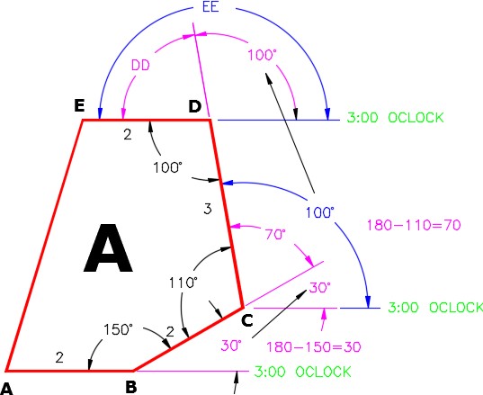
Study the figure and solutions for numbers 1 to 6. Solve the answers for numbers 7 to 11. (Figure Step 1)
Object A Solution:
| 1. Find the polar coordinate A TO B: | @2<0 |
| 2. Calculate the first angle: | 180 – 150 = 30 degrees |
| 3. Find the polar coordinate B TO C: | @2<30 |
| 4. Copy the 30 degree angle to the next corner. | |
| 5. Calculate the second angle: | 180 – 110 = 70 degrees |
| 6. Add the two angles: | 30 + 70 = 100 |
| 7. Find the polar coordinate C TO D: | @ < |
| 8. Copy the angle 100 to the next corner. | |
| 9. Calculate angle DD: | DD = |
| 10. Find angle EE: | EE = |
| 11. Find the polar coordinate D TO E: | @ < |
Step 2
Study the figure and find the solutions for numbers 1 to 11. (Figure Step 3)
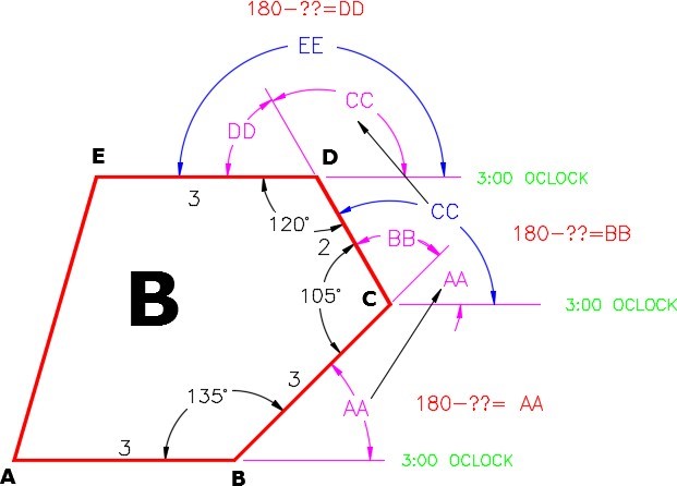
Object B Solution:
| 1. Find polar coordinate A TO B | @ < |
| 2. Calculate angle AA: | |
| 3. Find polar coordinate B TO C | @ < |
| 4. Copy angle AA to the next corner | |
| 5. Calculate angle BB | |
| 6. Find angle CC | |
| 7. Find polar coordinate C TO D | @ < |
| 8. Copy angle CC to the next corner | |
| 9. Calculate angle DD | |
| 10. Find angle EE | |
| 11. Find polar coordinate D TO E | @ < |
WORKALONG: Using the Polar Coordinate System – Part 2
Step 1
Start a new drawing using the template: 2D English.
Step 2
Save and name the drawing: AutoCAD 2D Workalong 10-1.
Step 3
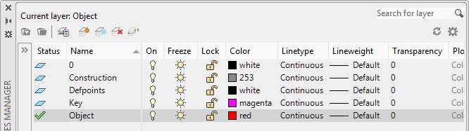
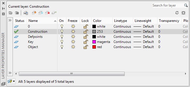
Create layers: Object and Construction. (Figure Step 3)
Step 4
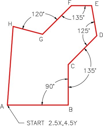
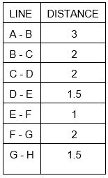
Set layer: Object as the current layer and enter the LINE command, as shown below, to draw the object. (Figure Step 4A)
Command: L
Specify first point: 2.5,4.5
(Start with an absolute Cartesian Coordinate.)
Specify next point or [Undo]: @3<0
(A to B is a horizontal line which is zero degrees.)
Specify next point or [Undo]: @2<90
(B to C is a vertical line at 90 degrees.)
(Figure Step 4B)
Specify next point or [Close/Undo]: @2<45
(C to D is 45 degrees positive.)
(Figure Step 4C)
Specify next point or [Close/Undo]: @1.5<100
(D to E)
(Figure Step 4D)
Specify next point or
[Close/Undo]: @1<180
(E to F is a horizontal line at 180 degrees.)
(Figure Step 4E)
Specify next point or [Close/Undo]: @2<225
(F to G)
(Figure Step 4F)
Specify next point or [Close/Undo]: @1.5<165
(G to H)
Specify next point or [Close/Undo]: C
(Use Close for H to A)
Specify next point or [Close/Undo]:
Command:
(Figure Step 4G)
Step 5
Your completed drawing should match the figure. (Figure Step 5)
Step 6
Save and close the drawing.
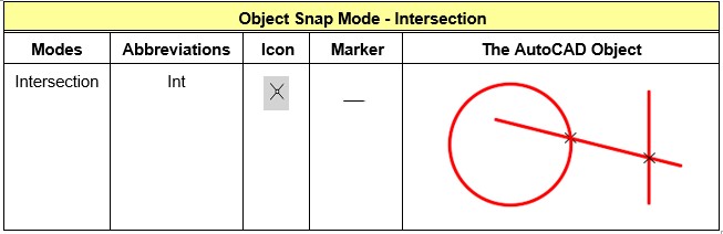
WORKALONG: Using the Object Snap Mode – Intersection
Step 1
Start a new drawing using the template: 2D English.
Step 2
Save and name the drawing: AutoCAD 2D Workalong 10-2.
Step 3
Create the layers: Object and Construction. Set layer: Construction as the current layer. (Figure Step 3)
Step 4
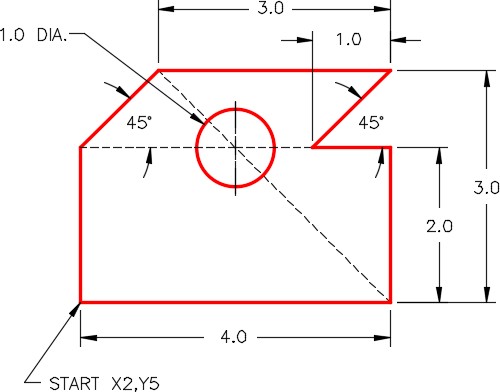
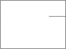
Refer to the figures and enter the LINE command, as shown below, to draw four construction lines. (Figure Step 4A and 4B)
Command: L
LINE Specify first point: 2,5
Specify next point or [Undo]: @4<0
Specify next point or [Undo]: @2<90
Specify next point or [Close/Undo]: @1<90
Specify next point or [Close/Undo]: @3<180
Specify next point or [Close/Undo]: @1<180
Specify next point or [Close/Undo]: @1<270
Specify next point or [Close/Undo]: C
Step 5
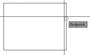
Ensure that osnap is enable and then draw an additional construction line by snapping to the endpoint of the existing line and 1 unit in the -X direction. (Figure Step 5A and 5B)
Step 6
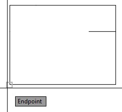
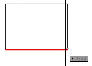
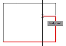
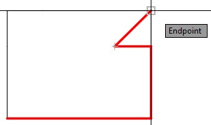
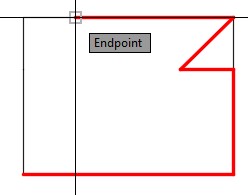
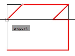
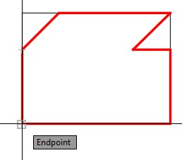
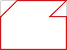
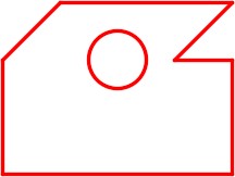
Set layer: Object as the current layer. Enter the LINE command and enable osnap. Draw the perimeter lines of the object by snapping to the endpoints of the construction lines. (Figure Step 6A, 6B, 6C, 6D, 6E, 6F, 6G, 6H, and 6J)

Step 7
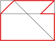
On layer: Construction , draw two construction lines by snapping to the endpoint of the existing lines as shown in the figure. (Figure Step 7)
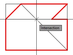
Step 8
Enter the CIRCLE command and draw a 1 diameter circle locating its center point by
snapping to intersection of the two construction lines you drew in Step 7. (Figure Step 8A and 8B)

Step 9
Freeze layer: Construction. (Figure Step 9)
Step 10
Save and close the drawing.
Key Principles
Key Principles in Module 10
- The Polar Coordinate System is used to draw lines using a distance and an angle from a known coordinate location.
- By default, an AutoCAD polar coordinate measures angles starting 0 degrees at 3:00 o’clock.
- In a polar coordinate, positive angles are measured counterclockwise and negative angles are measured clockwise.
- A polar coordinate is entered into AutoCAD as a distance, a less than symbol, and an angle. In all cases, the @ symbol must precede the distance.
Lab Exercise 10-1
Time allowed: 30 minutes.
| Drawing Name | Template | Units |
|---|---|---|
| AutoCAD 2D Lab 10-1 | 2D English | Inches |
| Layer Name | Objects on Layer | Color |
|---|---|---|
| Construction | Construction objects | 253 |
| Object | Lines | Red |
Step 1
Start a new drawing using the template shown above.
Step 2
Setup the layers using the Layering Scheme.
Step 3
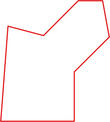
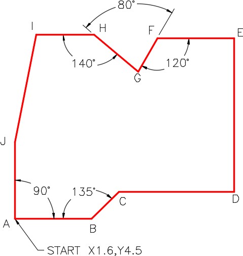
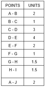
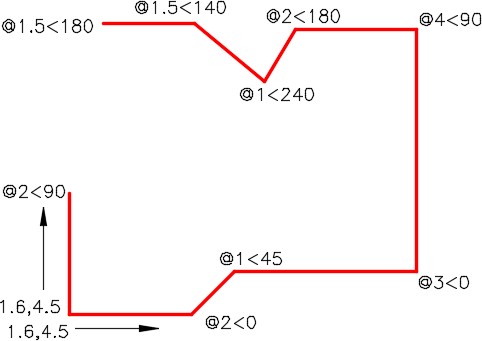
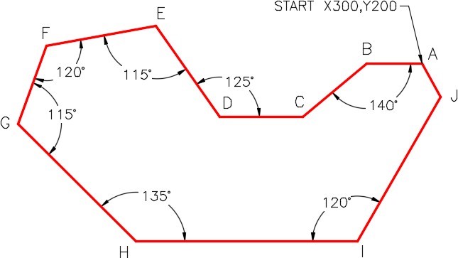
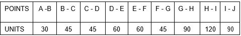
Draw the object shown in the figures using the layering scheme. (Figure Step 3A and 3B)
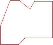
Completed Drawing
Step 4
Enter the UNITS command. In the Units dialogue box, set the Insertion Units to Inches.
Step 5
Check your drawing with the key. The key name is the same as the drawing name.
Step 6
If you have any errors, turn layer: Key off and correct your drawing. If you cannot correct it, start it over from the beginning.
Step 7
Turn layer: Key on to check your drawing. If it is still inaccurate, go back to Step 6.
Step 8
Turn layer: Key off.
Step 9
Save and close the drawing.
Hint1
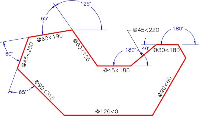
See the figure for the polar coordinates. (Figure Hint 1)
Hint 2
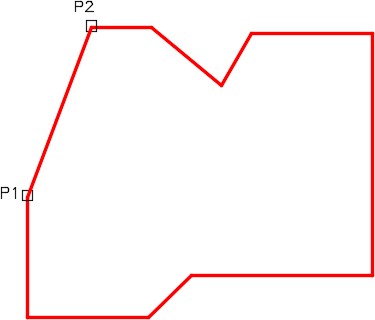
Draw the line from J to I by snapping to the endpoints. (Figure Hint 2)
Hint 3
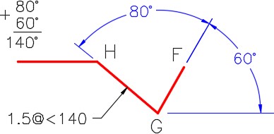
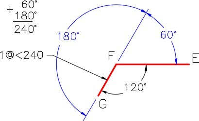
The solutions to the angles at G and F are shown in the figures. (Figure Hint 3A and 3B)
Lab Exercise 10-2
Time allowed: 40 minutes.
| Drawing Name | Template | Units |
|---|---|---|
| AutoCAD 2D Lab 10-2 | 2D Metric | Millimeters |
| Layer Name | Objects on Layer | Color |
|---|---|---|
| Construction | Construction objects | 253 |
| Object | Lines | Red |
Step 1
Start a new drawing using the template shown above.
Step 2
Setup the layers using the Layering Scheme.
Step 3
Draw the object shown in the figures using the layering scheme. (Figure Step 3A and 3B)
Completed Drawing
Step 4
Enter the UNITS command. In the Units dialogue box, set the Insertion Units to Millimeters.
Step 5
Check your drawing with the key. The key name is the same as the drawing name.
Step 6
If you have any errors, turn layer: Key off and correct your drawing. If you cannot correct it, start it over from the beginning.
Step 9
Save and close the drawing.
Hint 1
See the figure for the polar coordinates. (Figure Hint 1)
Lab Exercise 10-3
Time allowed: 40 minutes.
| Drawing Name | Template | Units |
|---|---|---|
| AutoCAD 2D Lab 10-3 | 2D Metric | Millimeters |
| Layer Name | Objects on Layer | Color |
|---|---|---|
| Angle Bracket | All drawing objects | Blue |
Step 1
Draw the front view of the angle bracket shown in the dimensioned drawing using the layering scheme. (Figure Step 1A, 1B, and 1C)
Step 2
All objects should be on layer Angle Bracket and display blue.
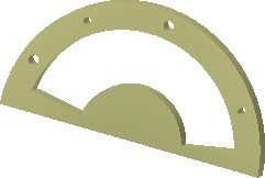
Angle Bracket
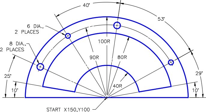

Completed Drawing
Step 3
Set the insertion units and check your drawing with the key. Turn layer: Key off and freeze layer: Construction.
Step 4
Save and close the drawing.
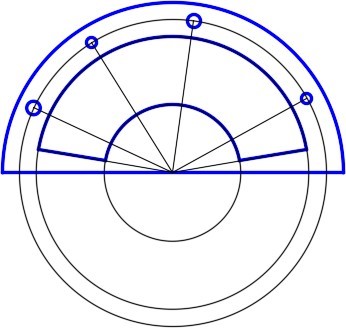
Hint 1
This figure shows my construction drawing objects. Your construction drawing objects do not have to match as there are may ways to construct an object. I use circles rather an arcs, whenever possible, as they are easier to construct. (Figure Hint 1)
 Angle A = 40 degrees
Angle B = 125 degrees
Angle C = 150 degrees
Angle D = 30 degrees
Angle E = 215 degrees
Angle F = 35 degrees
Angle G = 75 degrees
Angle H = 105 degrees
Angle J = 135 degrees
Angle K = 120 degrees
Angle L = 211 degrees
Angle M = 324 degrees
Object A Solution:
| 1. Find the polar coordinate A TO B: | @2<0 |
| 2. Calculate the first angle: | 180 – 150 = 30 degrees |
| 3. Find the polar coordinate B TO C: | @2<30 |
| 4. Copy the 30 degree angle to the next corner. | |
| 5. Calculate the second angle: | 180 – 110 = 70 degrees |
| 6. Add the two angles: | 30 + 70 = 100 degrees |
| 7. Find the polar coordinate C TO D: | @3<100 |
| 8. Calculate angle DD: | 180 – 100 = 80 degrees |
| 9. Find angle EE: | 100 + 80 = 180 degrees |
| 10. Find the polar coordinate D TO E: | @2<180 |
Object B Solution:
| 1. Find polar coordinate A TO B | @3<0 |
| 2. Calculate angle AA: | 180 – 135 = 45 degrees |
| 3. Find polar coordinate B TO C | @3<45 |
| 4. Copy angle AA to the next corner | |
| 5. Calculate angle BB | 180 – 105 = 75 degrees |
| 6. Find angle CC | 45 + 75 = 120 degrees |
| 7. Find polar coordinate C TO D | @2<120 |
| 8. Copy angle CC to the next corner | |
| 9. Calculate angle DD | 180 – 120 = 60 degrees |
| 10. Find angle EE120 + 60 = 180 degrees | |
| 11. Find polar coordinate D TO E | @3<180 |
