Module 14: Trimming and Extending
Learning Outcomes
When you have completed this module, you will be able to:
- Describe the geometry of regular polygons.
- Apply the TRIM and EXTEND commands to shorten and lengthen drawing objects at selected cutting edges.
Geometry Lesson: Regular Polygons
A polygon is defined as any plane figure bounded by straight lines. A regular polygon is a polygon that has equal angles, equal sides, and can be inscribed or circumscribed around a circle. AutoCAD has a command to automatically construct polygons and it will be taught in a future module. For now, it is important for you to be able to construct polygons using geometry.
The first nine regular polygons are shown in Figure 14-1.
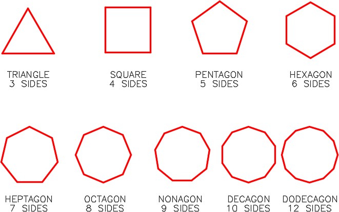
Regular Polygons
Any regular polygon can be inscribed in or circumscribed around a circle as shown, using a hexagon, in Figure 14-2.
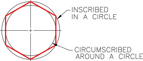
Inscribed and Circumscribed Regular Polygon
It is important to understand and know the geometry involved to construct a triangle, square, hexagon, and octagon as shown in Figure 14-3. Study each one and try to understand how they are constructed and the angles used to construct them.
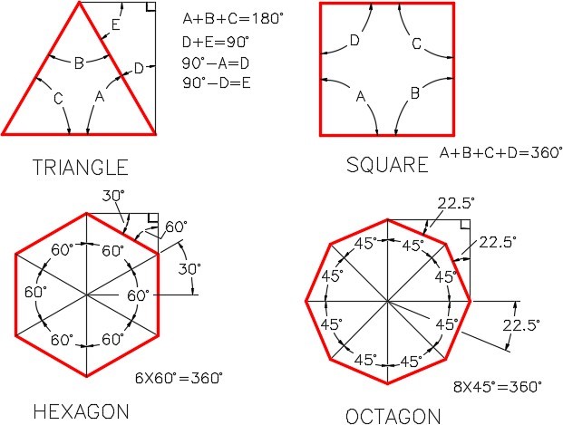
Geometry of Four Regular Polygons
The following are the steps used to draw a hexagon in an AutoCAD drawing. See Figure 14-4.
Step 1
Draw 6 lines on layer Construction from the center to each corner, 60 degrees apart.
Step 2
Draw six lines snapping from the end of one line to the end of the next line.
Step 3
Turn layer Construction off.
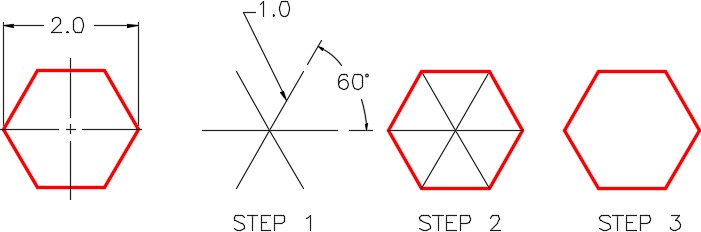
Drawing a Hexagon
Trimming and Extending
Not every object can be drawn using exact coordinates or locations as has been taught to this point in the book. There are times where it is essential that objects be drawn to approximate lengths and sizes and then trimmed or extended to their exact size and location. This does not mean that you can guess at the size and location of the objects. Objects must still be drawn with 100 percent accuracy. The length can be approximated and then adjusted using the TRIM or EXTEND commands. These two commands are a big part of you becoming more productive.
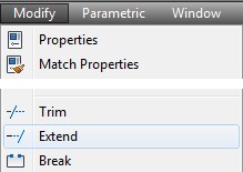
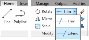
In AutoCAD 2021 there have been changes to the Trim and extend commands and the default settings will not produce the expected results in the following tutorials. The default MODE setting, QUICK, will give access to the [cutting edges/Crossing/mode/Project/erase] options, which should be set as explained later in this tutorial. Then, as a last step, the mode should be set to standard. This will produce the expected behavior of TRIM and EXTEND. If you do not see the above options, set the MODE to Quick, make the setting changes and then restore the MODE setting to Standard.
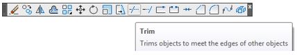
AutoCAD Command: TRIM
The TRIM command is used to shorten objects to meet the edges of other objects. It is not required for the object being trimmed to intersect with the object forming the cutting edge.
Shortcut: TR
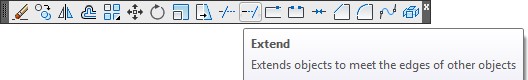
AutoCAD Command: EXTEND
The EXTEND command is used to lengthen objects to meet the edges of other objects. It is not required for the object being extended to intersect with the object forming the cutting edge.
Shortcut: EX
WORKALONG: Using the TRIM and EXTEND Commands
Step 1
Start a new drawing using the template: 2D English.
Step 2
Save and name the drawing: AutoCAD 2D Workalong 14-1.
Step 3
Create the layers: Object and Construction. Set layer: Construction as the current layer.
Step 4
Using the figures as a reference, enter the LINE command, as shown on the below, to draw the construction lines shown in Figure Step 4B. (Figure Step 4A and 4B)
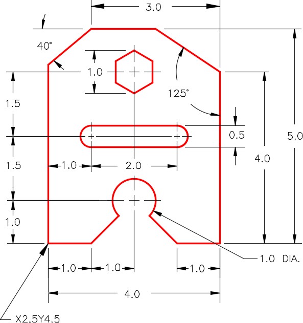
Command: L
Specify first point: 2.5,4.5
Specify next point or [Undo]: @1,0
Specify next point or [Undo]: @2,0
Specify next point or [Close/Undo]: @1,0
Specify next point or [Close/Undo]: @0,4
Specify next point or [Close/Undo]: @0,1
Specify next point or [Close/Undo]: @-3,0
Specify next point or [Close/Undo]: @2<220
Specify next point or [Close/Undo]:
Command: L
Specify first point: (end) P1
Specify next point or [Undo]: @0,5
Command: L
Specify first point: (end) P2
Specify next point or [Undo]: @1<145
(The length of this line can be any length but the direction must be accurate. I purposely drew it shorter to demonstrate the EXTEND command.)
Command:
Step 5
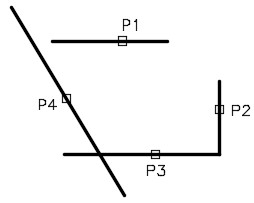
Enter the TRIM command as shown below. (Figure Step 5).
Command: TRIM
Current settings: Projection=UCS, Edge=None
Select cutting edges …
Select objects or <select all>:
Select object to trim or shift-select to extend or [Fence/Crossing/Project/Edge/eRase/Undo]: E
Enter an implied edge extension mode [Extend/No extend] <No extend>: E
Select object to trim or shift-select to extend or [Fence/Crossing/Project/Edge/eRase/Undo]:
Command:
Command: TRIM
Current settings: Projection=UCS, Edge=Extend
Select cutting edges …
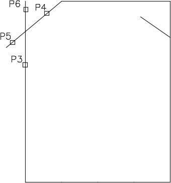
Select objects or <select all>: P3 1 found
Select objects: P4 1 found, 2 total
(These lines are the cutting edges.)
Select objects:
(Press enter or space.)
Select object to trim or shift-select to extend or [Fence/Crossing/Project/Edge/eRase/Undo]: P5
Select object to trim or shift-select to extend or [Fence/Crossing/Project/Edge/eRase/Undo]: P6
(These are the lines to trim. Select the line close to the end to be trimmed.)
Select object to trim or shift-select to extend or [Fence/Crossing/Project/Edge/eRase/Undo]:
Command:
Step 6
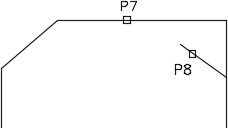
Enter the EXTEND command, as shown below, to extend the line to top line in object. (Figure Step 6A and 6B)
Command: EXTEND
Current settings: Projection=UCS, Edge=Extend
Select boundary edges …
Select objects or <select all>: P7 1 found
(The cutting edge.)
Select objects:
(Press enter or space.)
Select object to extend or shift-select to trim or [Fence/Crossing/Project/Edge/Undo]: P8
(The line to extend. Select the line close to the end that is to be extended.)
Select object to extend or shift-select to trim or [Fence/Crossing/Project/Edge/Undo]:
Command:
Step 7
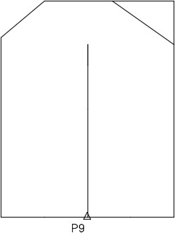
Draw three construction lines starting at the midpoint of the bottom line. (Figures Step 7)
Command: L
Specify first point: (mid) P9
Specify next point or [Undo]: @0,1
Specify next point or [Undo]: @0,1.5
Specify next point or [Close/Undo]: @0,1.5
Specify next point or [Close/Undo]:
Command:
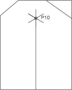
Step 8
Enter the LINE commands, as shown below, to insert the construction lines for the hexagon. Each line starts at the end of the construction line drawn in Step 7. (Figure Step 8)
Command: L
Specify first point: (end) P10
Specify next point or [Undo]: @.5<30
Specify next point or [Close/Undo]:
Command: L
Specify first point: (end) P10
Specify next point or [Undo]: @.5<90
Specify next point or [Close/Undo]:
Command: L
Specify first point: (end) P10
Specify next point or [Undo]: @.5<150
Specify next point or [Close/Undo]:
Command: L
Specify first point: (end) P10
Specify next point or [Close/Undo]: @.5<210
Specify next point or [Close/Undo]:
Command: L
Specify first point: (end) P10
Specify next point or [Undo]: @.5<270
Specify next point or [Close/Undo]:
Command: LINE Specify first point:
Command: L
Specify first point: (end) P10
Specify next point or [Undo]: @.5<330
Specify next point or [Close/Undo]:
Command:
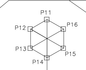
Step 9
Enter the LINE command, as shown below, to construct the lines for the hexagon. Ensure that you have Autosnap enabled and you snap to the endpoints of the lines. (Figure Step 9)
Command: L
Specify first point: (end) P11
Specify next point or [Undo]: (end) P12
Specify next point or [Undo]: (end) P13
Specify next point or [Close/Undo]: (end) P14
Specify next point or [Close/Undo]: (end) P15
Specify next point or [Close/Undo]: (end) P16
Specify next point or [Close/Undo]: (end) P11
Specify next point or [Close/Undo]:
Command:
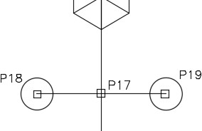
Step 10
Enter the LINE and CIRCLE commands, as shown below, to draw the slot. (Figure Step 10A and 10B)
Command: L
Specify first point: (end) P17
Specify next point or [Undo]: @1,0
Specify next point or [Undo]:
Command: L
Specify first point: (end) P17
Specify next point or [Undo]: @-1,0
Specify next point or [Undo]:
Command: C
Specify center point for circle or [3P/2P/Ttr (tan tan radius)]: (end) P18
Specify radius of circle or [Diameter]: D
Specify diameter of circle: .5
Command: C
Specify center point for circle or [3P/2P/Ttr (tan tan radius)]: (end) P19
Specify radius of circle or [Diameter] <0.2500>:
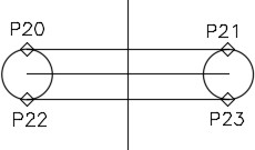
Command: L
Specify first point: (quad) P20
Specify next point or [Undo]: (quad) P21
Specify next point or [Undo]: Command: L
Specify first point: (quad) P22
Specify next point or [Undo]: (quad) P23
Specify next point or [Undo]:
Command:
Step 11
Enter the commands, as shown below, to draw the construction objects for the bottom arc. (Figure Step 11A and 11B)
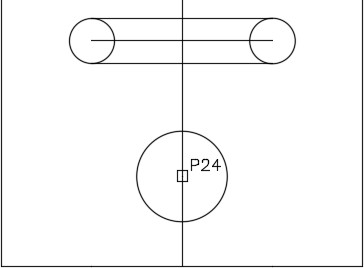
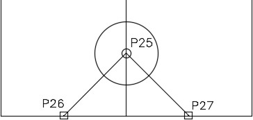
Command: C
Specify center point for circle or [3P/2P/Ttr (tan tan radius)]: (end) P24
Specify radius of circle or [Diameter]: D
Specify diameter of circle: 1
Command: L
Specify first point: (cen) P25
Specify next point or [Undo]: (end) P26
Specify next point or [Undo]:
Command: L
Specify first point: (cen) P25
Specify next point or [Undo]: (end) P27
Specify next point or [Undo]:
Command:
Step 12
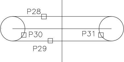
Enter the TRIM command, as shown below, to create the slot. (Figure Step 12A and 12B)
Command: TRIM
Current settings: Projection=UCS, Edge=Extend
Select cutting edges …
Select objects or <select all>: P28 1 found
Select objects: P29 1 found, 2 total
Select objects:
(Press enter or space.)
Select object to trim or shift-select to extend or [Fence/Crossing/Project/Edge/eRase/Undo]: P30
Select object to trim or shift-select to extend or [Fence/Crossing/Project/Edge/eRase/Undo]: P31
Select object to trim or shift-select to extend or [Fence/Crossing/Project/Edge/eRase/Undo]:
Command:
Step 13
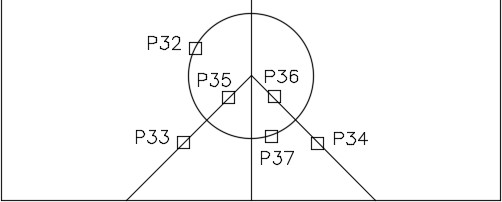
Enter the TRIM command, as shown below, to create the bottom arc. (Figure Step 13A and 13B)
Command: TRIM
Current settings: Projection=UCS, Edge=Extend
Select cutting edges …
Select objects or <select all>: P32 1 found
Select objects: P33 1 found, 2 total
Select objects: P34 1 found, 3 total
Select objects:
(Press enter or space)
Select object to trim or shift-select to extend or [Fence/Crossing/Project/Edge/eRase/Undo]: P35
Select object to trim or shift-select to extend or [Fence/Crossing/Project/Edge/eRase/Undo]:P36
Select object to trim or shift-select to extend or [Fence/Crossing/Project/Edge/eRase/Undo]: P37
Select object to trim or shift-select to extend or [Fence/Crossing/Project/Edge/eRase/Undo]:
Command:
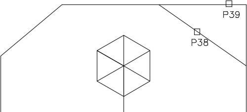
Step 14
Enter the TRIM command, as shown below, to trim the line on the top right. (Figure Step 14A and 14B)
Command: TRIM
Current settings: Projection=UCS, Edge=Extend
Select cutting edges …
Select objects or <select all>: P38 1 found
Select objects:
(Press enter or space)
Select object to trim or shift-select to extend or [Fence/Crossing/Project/Edge/eRase/Undo]: P39
Select object to trim or shift-select to extend or
[Fence/Crossing/Project/Edge/eRase/Undo]:
Command:
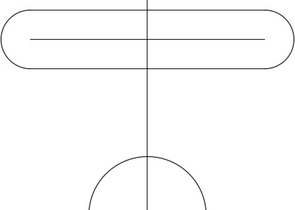
Step 15
Change the layer of the objects that you want to reside on layer: Object. (Figure Step 15)
Step 16
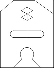
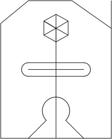
Freeze layer: Construction. Your completed drawing should appear as shown in the figure. (Figure Step 16)
Step 17
Save and close the drawing.
MUST KNOW: The Edge option in the TRIM and EXTEND commands should always be set to Extend as shown below. Step 5 will show you how to set it. See also the 2nd paragraph in the notes on Trim an Extend.
Command: TRIM
Current settings: Projection=UCS, Edge=Extend
Command: TRIM (See Figure Step 1.)
Select objects:
Select object to trim or shift-select to extend or [Fence/Crossing/Project/Edge/eRase/Undo]: E
(Enter the Edge option.)
Enter an implied edge extension mode [Extend/No extend] <No extend>: E
(Set it to Extend. This allows you to trim or extend when the objects do not physically touch.)
Select object to trim or shift-select to extend or [Fence/Crossing/Project/Edge/eRase/Undo]: P5
Select object to trim or shift-select to extend or [Fence/Crossing/Project/Edge/eRase/Undo]: P6
Select object to trim or shift-select to extend or [Fence/Crossing/Project/Edge/eRase/Undo]: P7
(Press and hold down the Shift key to change to the EXTEND command.)
Select object to trim or shift-select to extend or [Fence/Crossing/Project/Edge/eRase/Undo]: P8
Select object to trim or shift-select to extend or [Fence/Crossing/Project/Edge/eRase/Undo]: P9
Select object to trim or shift-select to extend or [Fence/Crossing/Project/Edge/eRase/Undo]: P10
Select object to trim or shift-select to extend or [Fence/Crossing/Project/Edge/eRase/Undo]:
Command:
Key Principles
Key Principles in Module 14
- To improve your drawing productivity, draw the location and direction of objects with 100 percent accuracy but at an arbitrary length. Adjust the length with the TRIM or EXTEND commands.
- With both the TRIM and EXTEND commands, select the cutting edge objects first, press the Enter or Space key, and then select the object(s) to trim or extend.
- The TRIM and EXTEND commands are interchangeable by holding down the Shift key to change from one command to the other.
Lab Exercise 14-1
Time allowed: 40 minutes.
| Drawing Name | Template | Units |
|---|---|---|
| AutoCAD 2D Lab 14-1 | 2D English | Inches |
| Layer Name | Objects on Layer | Color |
|---|---|---|
| Construction | Construction objects | 253 |
| Object 1 | All objects | Red |
Step 1
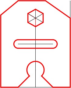
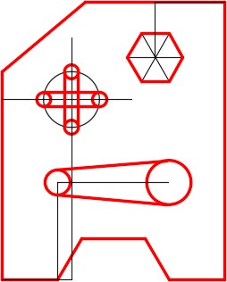
Draw the object shown in the figure using the layering scheme. (Figure Step 1A and 1B)
Step 2
Set the insertion units and check your drawing with the key.
Step 3
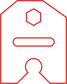
Turn layer: Key off and freeze layer: Construction.
Step 4
Save and close the drawing.
Hint 1
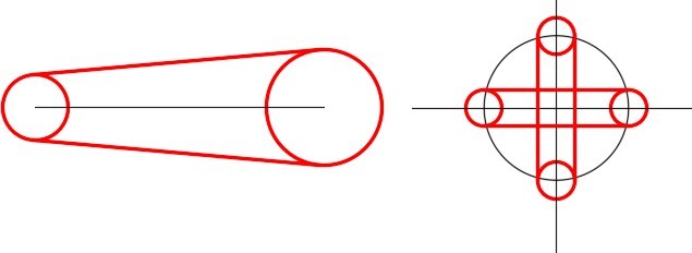
Draw the lines in the correct location and direction but to any length and then trim or extend them. (Figure Hint 1)
Hint 2
The lines in Figure Hint 2A must be drawn tangent to tangent (see Module 12) while the lines in Figure Hint 2B can be draw either tangent to tangent or quad to quad. (Figure Hint 2A and 2B)
Hint 3
The figure shows the construction lines. (Figure Hint 3)
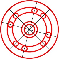
Lab Exercise 14-2
Time allowed: 30 minutes.
| Drawing Name | Template | Units |
|---|---|---|
| AutoCAD 2D Lab 14-2 | 2D Metric | Millimeters |
| Layer Name | Objects on Layer | Linetype | Color |
|---|---|---|---|
| Construction | Construction objects | Continuous | 253 |
| Circle 1 | Outside circle | Center2 | Red |
| Circle 2 | Inside circles | Continuous | Red |
| Slots | Slots | Dashdot2 | Blue |
Step 1
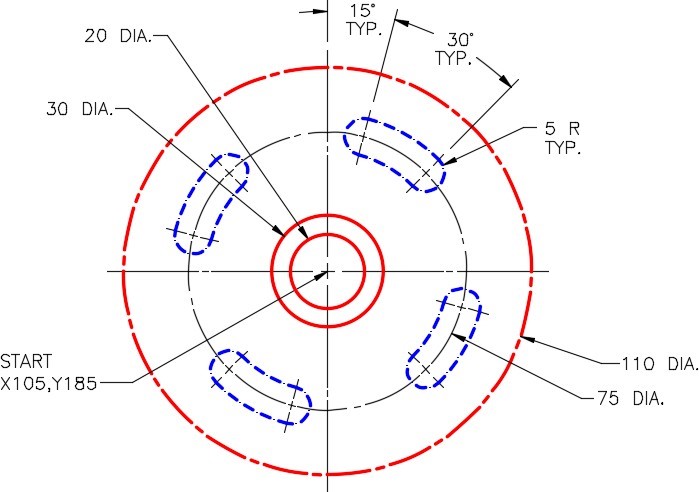
Draw the object shown in the figure using the layering scheme. (Figure Step 1A and 1B)
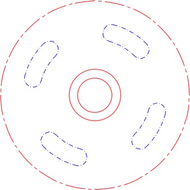
Completed Drawing
Step 2
Set the insertion units and check your drawing with the key.
Step 3
Turn layer: Key off and freeze layer: Construction.
Step 4
Save and close the drawing.
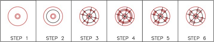
Hint 1
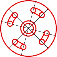
Step 1
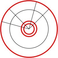
Draw only four construction lines at the correct angle as shown in the figure. Extend them to other side of the large circle. That will save you from drawing all 8 lines. (Figure Step 1A and 1B)
Step 2
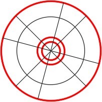
Draw 8 circles locating their centers at the intersection of the lines and circle. (Figure Step 2)
Step 3
Draw 2 large circles by showing AutoCAD the radius by snapping to the intersection of the small circle and line. (Figure Step 3)
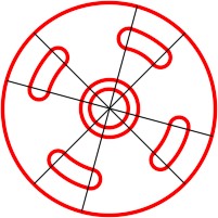
Step 4
Trim the large circles. (Figure Step 4)
Step 5
Trim the slots. (Figure Step 5)
Lab Exercise 14-3
Time allowed: 40 minutes.
| Drawing Name | Template | Units |
|---|---|---|
| AutoCAD 2D Lab 14-3 | 2D Metric | Millimeters |
| Layer Name | Objects on Layer | Color |
|---|---|---|
| Concrete Block | All objects | Blue |
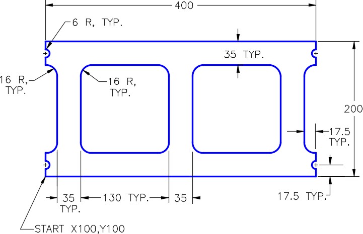
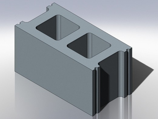
Step 1
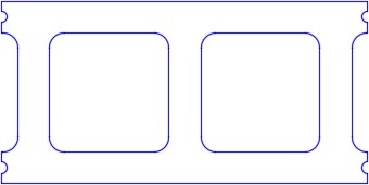
Draw the top view of the concrete block shown in the figure using the layering scheme. (Figure Step 1A, 1B, and 1C)
Step 2
Set the insertion units and check your drawing with the key. Turn layer: Key off and freeze layer: Construction.
Step 3
Save and close the drawing.
