Module 37: Dimensioning- Part 1
Learning Outcomes
When you have completed this module, you will be able to:
- Define the 11 basic dimensioning terms.
- Describe the properties of associative and exploded dimensions.
- Apply the DIMASSOC and DIMSTYLE commands to control and modify the appearance of dimensions.
- Create a dimension style and set the dimension variables for both an english and metric drawing.
- Apply the BREAK and DIMCENTER commands to draw center lines.
Dimensioning
Dimensioning is the process of adding size descriptions to objects in the drawing. After the dimensioned are inserted, the layout can be plotted and used for construction or reference. Up to this point in the book, only shape description have been defined to the object by describing its size and location. Since AutoCAD knows the exact size of the objects in the drawing, you only have to enter the type and location of the dimension you want to insert and AutoCAD will do the rest.
Since there is a lot to learn, dimensioning is a complex but not a difficult subject. Therefore, in the AutoCAD 2D book, only learning to control the appearance, inserting, and editing the basic dimension types is taught. When you complete the AutoCAD 2D book, you will be able to completely dimension a drawing for most applications.
Associative verses Exploded Dimensions
An associative dimension is intelligent, similar to an associative hatch pattern. They are tied to the object they are dimensioning. An exploded dimension is simply a collection of AutoCAD drawing objects indicating a measurement on the object. It has no relation to the object it is dimensioning. An associative dimension and exploded dimension do not appear any different on the drawing and you cannot tell them apart by looking at them. The differences between them are as follows:
- The dimensions of objects dimensioned with associative dimensions, when modified with most editing commands, will change to reflect the changes to the size of the object. The dimensions of objects that are dimensioned with an exploded dimension, when modified, will not change.
- Associative dimensions are harder to edit than exploded dimensions because they are inserted as blocks. An exploded dimension is inserted with individual drawing objects. If an associative dimension is exploded, it will be converted into an exploded dimension.
- If the properties of the dimensioning style of an associative dimension is modified, all dimensions on the drawing, using that style, will change. For example, if the user changes the height of dimension text, change it once in the dimensioning style and all existing associative dimensions, using that style, will automatically display the new size.
Definition Points
Definition points are points that are automatically inserted on the drawing when an associative dimension is inserted. One definition point is inserted for each end of an extension line or on opposite sides of a circle or an arc. The points are automatically placed on layer Defpoints. If the Defpoints layer does not exist in the drawing, it will be created automatically when the first associative dimension is inserted on that drawing. The Defpoints layer cannot be deleted or purged.
These inserted points are the intelligent part of the associative dimension. It is these points that cause the dimension to automatically update since they are moved in the object editing commands and the dimension follows them. In an associative dimension, the points are attached to the object. Therefore, almost all editing commands move the points with the object.
The definition points will not plot and are not affected by the point type and size appearance. If you explode an associative dimension, the points attached to it will automatically be erased.
Dimensioning Styles
A dimensioning style is similar to a text style. A dimensioning style controls the way dimensions appear on your drawing. There are many different settings in a dimensioning style so it will take you a lot of practice to get used to setting them.
New styles can be created or existing dimensioning styles edited with the DIMSTYLE command. AutoCAD uses the current dimensioning style properties when inserting dimensions with any dimensioning command. By modifying a dimension style, you can update all existing associative dimensions on the drawing inserted with that style.
Standard Dimensioning Style
The Standard dimensioning style exists in every drawing and cannot be deleted. Even though the Standard style can be used, it is not a good practice to use it. Create and name your own styles.
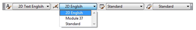
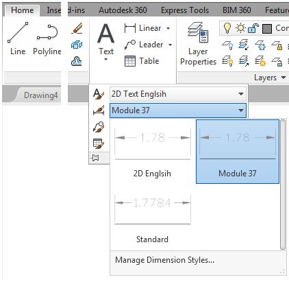
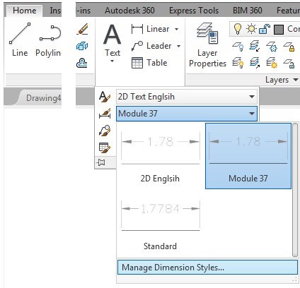
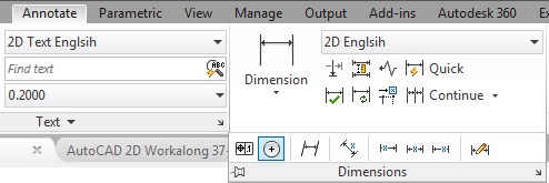
USER TIP: Use the Styles toolbar or the Home ribbon to pull down a list and select a name to change the current dimensioning style for the current drawing. When the list is not currently being pulled down, it displays the current dimension style.
Drafting Lesson: Basic Dimensioning Terms
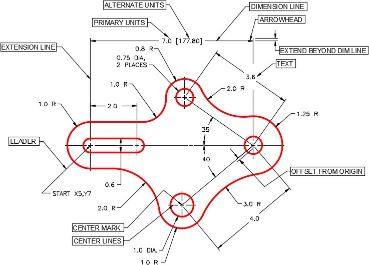
Figure 37-1 shows the 11 basic dimensioning terms that you should know when setting dimensioning styles.
AutoCAD Command: DIMASSOC
The DIMASSOC system variable is used to enable either associative, non-associative, or exploded dimensions being inserted by dimensioning commands.
Command: DIMASSOC
Enter new value for DIMASSOC <2>: 0
Command:
0 – Dimensions will be inserted as exploded dimensions.
1 – Dimensions will be inserted as non-associative dimensions.
2 – Dimensions will be inserted as associative dimensions.
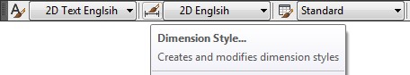
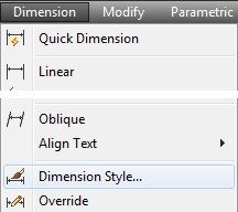
AutoCAD Command: DIMSTYLE
The DIMSTYLE command is used to create or modify dimensioning styles.
Shortcut: DDIM
WORKALONG: Creating and Editing Dimension Styles
Step 1
Start a new drawing using the template: 2D Layout English.
Step 2
Save and name the drawing: AutoCAD 2D Workalong 37-1.
Step 3
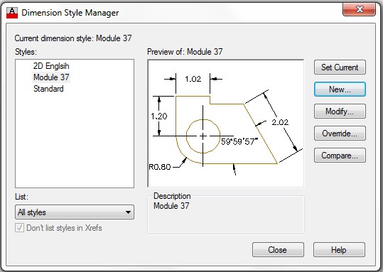
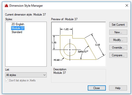
Enter the DIMSTYLE command. It will open the Dimension Style Manager dialogue box. (Figure Step 3)
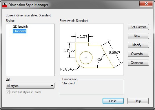
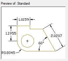
Step 4
Notice the graphic in the Preview of: window. It displays a pictorial view of how the dimensions, using current dimensioning style, would appear on a drawing. As changes are made to the current dimensioning style, the preview window will change to reflect those changes. (Figure Step 4)
Step 5
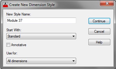
Click the New button. It will open the Create New Dimension Style dialogue box. In the New Style Name: box, enter the name: Module 37 and then click the Continue button. (Figure Step 5)
Step 6
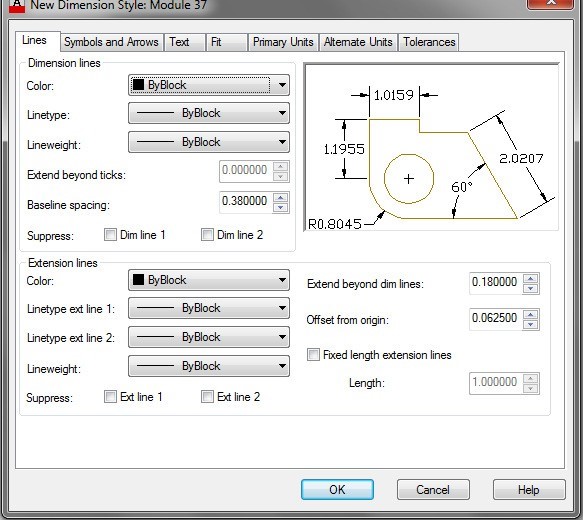
In the Dimension Style dialogue box, enable the Lines tab. (Figure Step 6)
Step 7
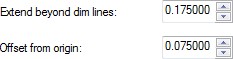
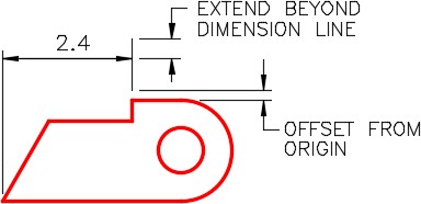
In the Extension lines area, change the Extend beyond dim lines: box to 0.1750 and the Offset from origin: box to 0.075. Figure Step 7B shows which dimension style variables you are setting. (Figure Step 7A and 7B)
Step 8
Enable the Symbols and Arrows tab. (Figure Step 8)
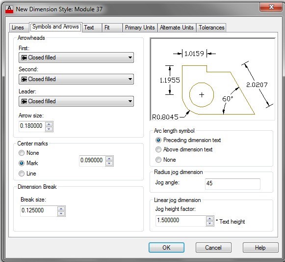
Step 9
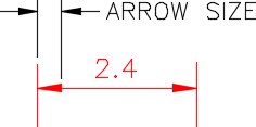
In the Arrowheads area, set the Arrow size: to 0.1750. (Figure Step 9A and 9B)
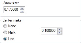
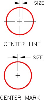
Step 10
In the Center marks area, enable Line and set it to 0.1000 as shown in Figure Step 9A. (Figure Step 10)
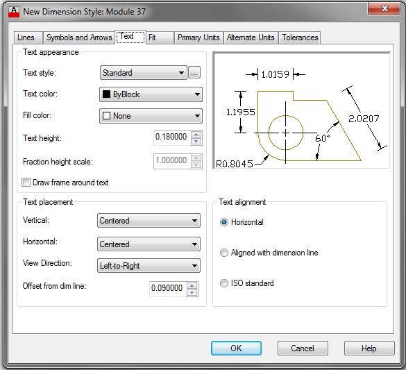
Enable the Text tab. (Figure Step 11)
Step 12
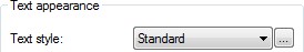
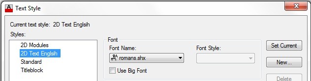
In the Text appearance area and Text style box, select the … box. (Figure Step 12)
Step 13
Step 12 will open the Text Style dialogue box. This is the same dialogue box that you open when you use the STYLE command. Using what you already learned, set the current text style to: 2D Text English with the font: romans.shx. (Figure Step 13)

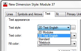
Step 14
In the Text appearance area, pull down the list of available text styles in the Text style box and select style: 2D Text English. Set the text height to 0.1500 in the Text height box. (Figure Step 14A and 14B)

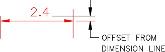
Step 15
In the Text placement area, set the Offset from dim line to 0.1000. (Figure Step 15A and 15B)

Step 16
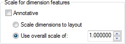
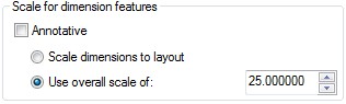
Enable the Fit tab. Ensure that the settings in your dialogue box match the figures. Ensure that the Use of Overall scale of is set to 1.00000. (Figure Step 16A and 16B)

Step 17
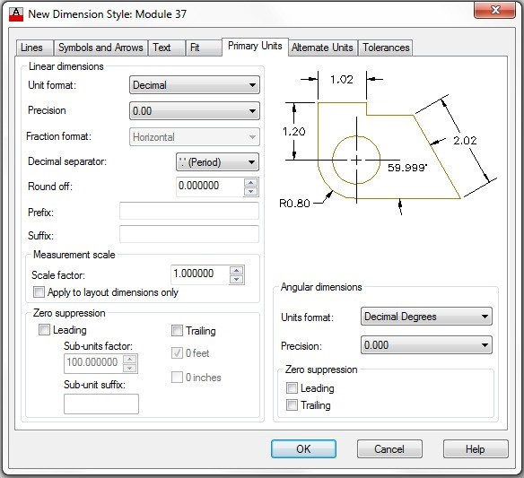
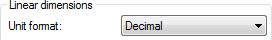
Enable the Primary Units tab. (Figure Step 17)
Step 18
In the Linear dimensions area, set the Precision to two decimal places. (Figure Step 18)
Step 19
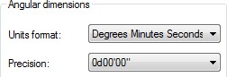
In the Angular dimensions area, set the Units format to Degrees Minutes Seconds and set the Precision to 0d00’00”. (Figure Step 19)
Step 20
Click OK and you will return to the Dimension Style Manager dialogue box. Click Close. (Figure Step 20)
Step 21
Save and close the drawing.
Drafting Lesson: Center Lines
In multiview drawings, the center line is used to indicate the location of the axis of symmetry. Placing center lines on all objects that have a symmetrical shape will help the reader and save the you from inserting a lot of dimensions as you will see in future modules. Below are some examples of typical applications of the use of center lines in a multiview drawing.
A ‘ C ‘ with an ‘ L ‘ through it is the symbol for a center line. Center lines are drawn as repeating long and short lines. See Figure37-2.

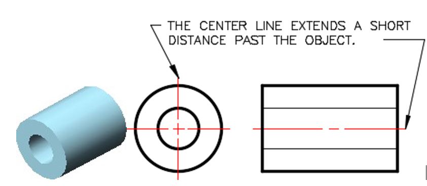
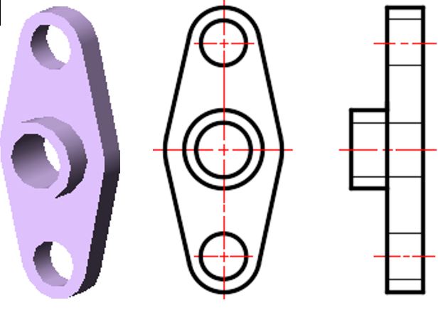
Figure 37-3 shows a center line indicating the center of the circle with two short lines called a center mark intersecting at the center. Note in the right sideview, the center line follows the length of the cylinder.
When the symmetry ends, so does the center line.
Note how the center line ends on the left side of the arc. See Figure 37-4
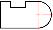
Figure 37-5 shows the center lines along with the hidden lines that indicate a hole going through the object. The center line on the top and bottom circles stops at the circle.
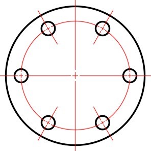
In Figure 37-6, note how center lines are drawn for an array of circles.
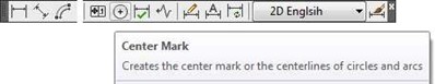
AutoCAD Command: DIMCENTER
The DIMCENTER command is used to insert center lines or center marks on circles or arcs.
Shortcut: none
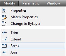
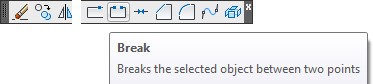
AutoCAD Command: BREAK
The BREAK command is used to break an object into two objects.
Shortcut: BR

WORKALONG: Drawing Center Lines
Step 1
Open the drawing: AutoCAD 2D Workalong 37-1. At the same time, open the drawing: AutoCAD 2D Workalong 15-2. With the drawing: AutoCAD 2D Workalong 15-2 as the current drawing, using the COPYBASE command and the base point of the 0,0, use a window and select all drawing objects.
Step 2
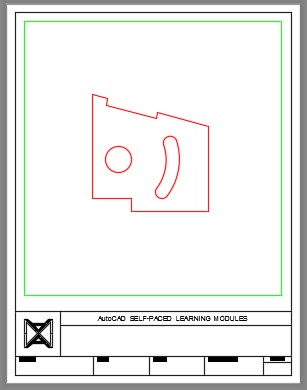
Change the current drawing to: AutoCAD 2D Workalong 37-1. Enter the PASTECLIP command and paste the objects using the insert point of 0,0. (Figure Step 2)
Step 3
Using the SAVEAS command, save the drawing with the name: AutoCAD 2D Workalong 37-2.
Step 4
Enable layout: Module Layout A. Change the current space to Paper. On layer: Viewport, create a viewport. Set the scale of the viewport to 0.75:1 and lock the display. (Figure Step 4)
Step 5
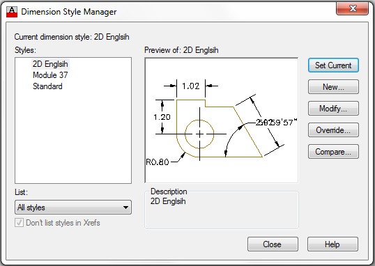
Using the DDIM command, open the Dimension Style Manager dialogue box. Set the current dimensioning style: Module 37. (Figure Step 5)
Step 6
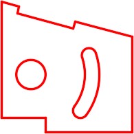
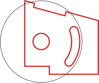
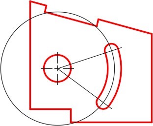
On layer: Construction, draw a construction circle using the center of the small circle as the center and select the radius by eye. Make it a short distance outside of the arc. (Figure Step 6)
Step 7
Set layer: Center Lines as the current layer.
Step 8
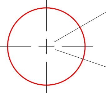
Enter the DIMCENTER command. When prompted, select the circle. It will insert center lines in the circle. (Figure Step 8)

Step 9
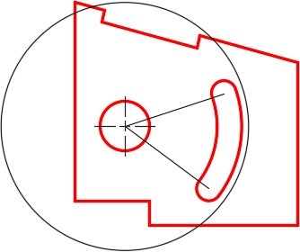
Draw two lines from the center of the small circle to the center of the small arcs as shown in the figure. (Figure Step 9)
Step 10
Using the EXTEND command, extend the lines to the large construction circle. (Figure Step 10)

Step 11
Turn layer: Construction off. Draw a circle on layer: Center Lines with the center at the center of the small circle and the radius as the center of the arc. Ensure that you use snap mode to snap to the exact centers of the circle and the arc. (Figure Step 11)
Step 12
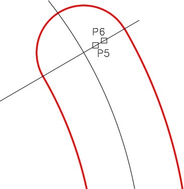
Ensure that object snap is disabled and enter the BREAK command as shown below. Make sure that you select location P1 first and then P2. Since arcs are constructed counterclockwise, you also have to break them counterclockwise. (Figures Step 12A and 12B)
Command: BREAK
select object: P1
Specify second break point or [First point]: P2
(The locations P1 and P2 can be selected by eye. This is a center line so the exact length is not that important. Try to match the figure as best you can.)
Command:

Step 13
Using the BREAK command, break the end off of the center line. Select the location P3 for the first point and for the second point, select anywhere past the end of the line. This will remove everything to the end of the line from point P3. (Figure Step 13)
Step 14
Using the BREAK command, break the end off of the other center line. (Figure Step 14)
Step 15
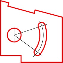
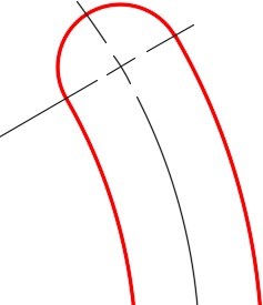
Zoom in on the small arc and break a small part of the line as shown in the figure. Do that 7 more times to draw the center lines for the arcs. It is best to zoom in close and break the lines by eye. The more you practice this, the better you will get doing it. (Figure Step 15A, 15B, and 15C)
Step 16
Using what you learned in this workalong, draw the center line for the slot at the top. The center line runs from the center of the circle perpendicular to the line, then extend it. You will have to add a construction line to extend to. (Figure Step 16)
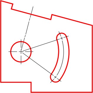
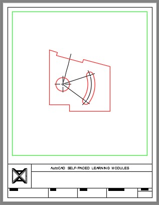
Step 17
The layout should appear as shown in the figure. (Figure Step 17)
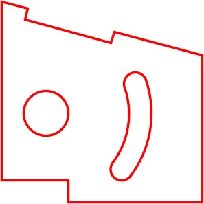
Step 18
Change the current space to Model. Your drawing should appear as shown in the figure. Since the center lines are in Paper space, the should not display. (Figure Step 18)
Step 19
Change the current space back to Paper space. (Figure Step 19)

Step 20
Save and close the drawing.
MUST KNOW: The Scale for Dimension Features area, located on the Fit tab, allows you to select the scale factor you want applied to the dimensioning features when a dimension is inserted. This can be a very useful item and will save you time. For example, if you set a dimension style for drawing units in inches and you want the samefeature sizes for a millimeter drawing, set the Use of overall scale of 25 since there are 25.4 mm in an inch. Experiment with this number until you like the look of your dimensions. This number does not effect the actual dimensions, only the dimension features.
Key Principles
Key Principles in Module 37
- Associative dimensions are dimensions that are intelligent, similar to an associative hatch pattern and are tied to the object they are dimensioning. An exploded dimension is simply a collection of AutoCAD objects indicating a measurement on the object and has no relation to the object it is dimensioning.
- Definition points are points that are automatically inserted, on layer Defpoints, on the drawing by dimensioning commands for associative dimensions. The Defpoints layer cannot be deleted or purged from the drawing.
- A dimensioning style controls the way your dimensions appear in your drawing. When a dimension is inserted, it is assigned the property of the current dimension style and uses the style properties.
Lab Exercise 37-1
Time allowed: 30 minutes.
| Drawing Name | Template | Units |
|---|---|---|
| AutoCAD 2D Lab 37-1 | 2D Layout English | Inches |
Step 1
Start a new drawing with the template shown above. Save and name the drawing: AutoCAD 2D Lab 37-1. At the same time, open the drawing: AutoCAD 2D Lab 13-1. Set drawing: AutoCAD 2D Lab 13-1 as the current drawing. Using the COPYBASE command and the base point of the 0,0, select all of the objects in the drawing.
Step 2
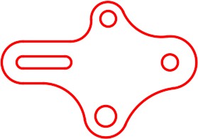
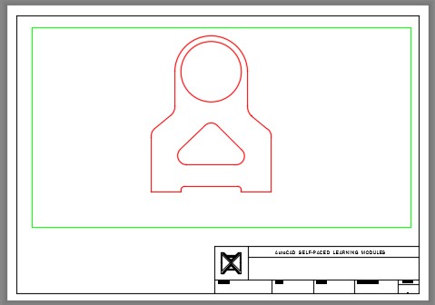
Change the current drawing to: AutoCAD 2D Lab 37-1. Enter the PASTECLIP command and paste the objects using the insert point of 0,0. (Figure Step 2)
Step 3
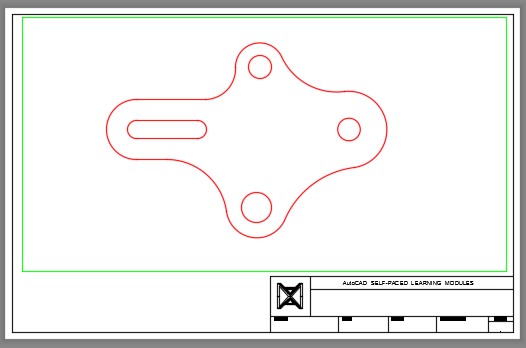
Enable layout: Module Layout C. On layer: Viewport, create a viewport. Set the scale of the viewport to 1.5:1 and lock the display. (Figure Step 3)
Step 4
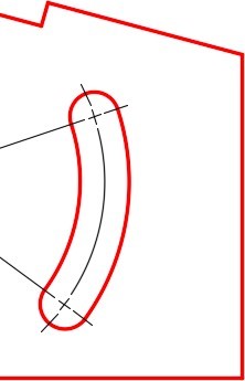
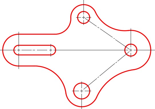
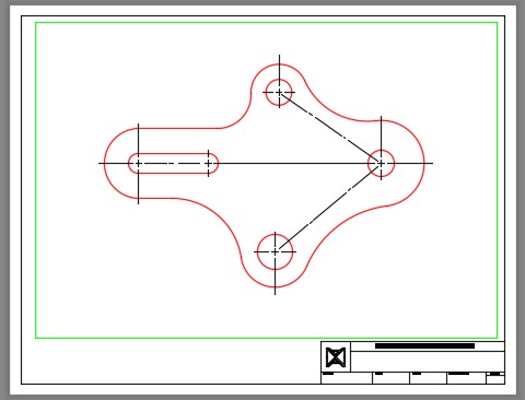
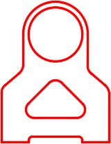
In Paper space, on layer: Center Lines, draw the center lines as shown in the figure. (Figure Step 4A and 4B)
Step 5
Save and close the drawing.
Lab Exercise 37-2
Time allowed: 30 minutes.
| Drawing Name | Template | Units |
|---|---|---|
| AutoCAD 2D Lab 37-2 | 2D Layout Metric | Millimeters |
Step 1
Start a new drawing with the template shown above. Save and name the drawing: AutoCAD 2D Lab 37-2. At the same time, open the drawing: AutoCAD 2D Lab 12-2. Set drawing: AutoCAD 2D Lab 12-2 as the current drawing. Using the COPYBASE command and the base point of the 0,0, select all of the objects in the drawing.
Step 2
Change the current drawing to: AutoCAD 2D Lab 37-2. Enter the PASTECLIP command and paste the objects using the insert point of 0,0. (Figure Step 2)
Step 3
Enable layout: Module Layout A3. On layer: Viewport, create a viewport. Set the scale of the viewport to 1.2:1 and lock the display. (Figure Step 3)
Step 4
In Paper space, on layer: Center Lines, draw the center lines as shown in the figure. Figure Step 4A and 4B)
Step 5
Save and close the drawing.
Lab Exercise 37-3
Time allowed: 30 minutes.
| Drawing Name | Template | Units |
|---|---|---|
| AutoCAD 2D Lab 37-3 | 2D Layout English | Inches |
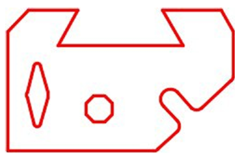
Step 1
Start a new drawing with the template shown above. Save and name the drawing: AutoCAD 2D Lab 37-3. At the same time, open the drawing: AutoCAD 2D Lab 15-1. Set drawing: AutoCAD 2D Lab 15-1 as the current drawing. Using the COPYBASE command and the base point of the 0,0, select all of the objects in the drawing.
Step 2
Change the current drawing to: AutoCAD 2D Lab 37-3. Enter the PASTECLIP command and paste the objects using the insert point of 0,0. (Figure Step 2)
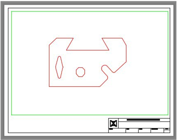
Step 3
Enable layout: Module Layout C. On layer: Viewport, create a viewport. Set the scale of the viewport to 1.25:1 and lock the display. (Figure Step 3)
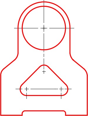
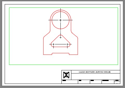
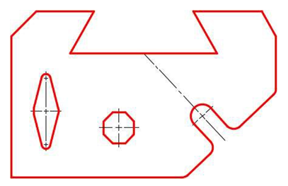
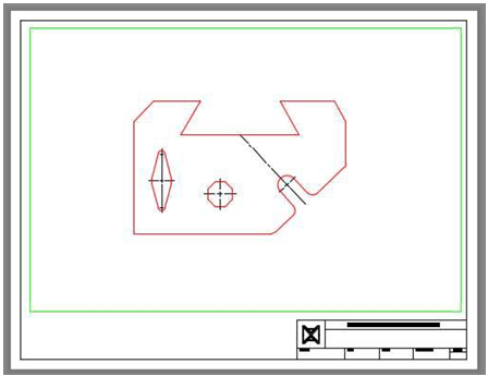
Step 4
In Paper space, on layer: Center Lines, draw the center lines as shown in the figure.
Step 5
Save and close the drawing.
