Module 5: Layers
Learning Outcomes
When you have completed this module, you will be able to:
- Describe AutoCAD’s layering system.
- Apply the LAYER command to create, toggle on/off, thaw/freeze, lock/unlock, select color, and set the current layer in the current drawing.
Layers
AutoCAD’s layering system is one of its most important features. Layers allow you to organize, segregate, set the drawing object’s color and linetype, control the visibility, and manage plotting of the drawing.
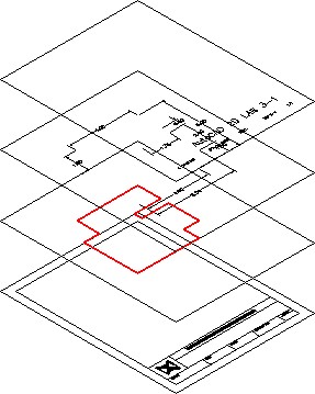
Think of layering as being able to draw on transparent overlays with each overlay containing relevant or grouped objects as shown in Figure 5-1. When all of the overlays are stacked together as shown in Figure 5-2, you can see and work on all of them. At any time, while you are working on drawing or printing it, you can control the layer’s visibly.
There is no limit to the number of layers that can be created in an AutoCAD drawing. Layers can be named by you or you can allow AutoCAD to automatically name them. A color, linetype, lineweight, and plot style can also be assigned. In this module, only naming and assigning a color to layers will be taught.
In addition to what was just discussed, the visibility of each layer can be controlled by toggling layers off or on and freezing or thawing them. A layer can also be locked to prevent objects on them from being modified.
AutoCAD’s Special Layer
AutoCAD has a special layer, named 0 (the number zero). Each new drawing created in AutoCAD will automatically contain this layer. It cannot be deleted or renamed. The importance of layer 0 will be discussed further in future modules.
The Current Layer
The current layer is the layer that AutoCAD will place all newly created drawing objects on. One layer is current at all times. The current layer can be turned off but never frozen. You can change which layer is the current layer at any time.
ByLayer vs ByObject
AutoCAD assigns the color, linetype, and lineweight properties to drawing objects either ByLayer or ByObject. In the AutoCAD 2D book, all work is done ByLayer. An easy way for you to check if you are working ByLayer is to look at the first three boxes in Properties menu as shown in Figures 5-3 and 5-4.
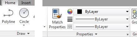

The three properties boxes should always display the words ByLayer as shown in the figure.
Simply, ByLayer means that when a drawing object is inserted into the drawing or an existing drawing object is regenerated, it looks in the drawing’s database to see what color, linetype, and lineweight it should display. If it is set ByLayer, it checks what layer the drawing object resides on and displays the color, linetype, and lineweight assigned to that layer. Most company standards require the color, linetype, and lineweight properties of their drawings to be drawn Bylayer.
It is important to know the different between a layer that is Off and a layer that is Frozen. A layer that is Off does NOT display but WILL regenerate. A layer that is Frozen does NOT display and will NOT regenerate. The importance of this will become apparent in future AutoCAD 2D modules.
Study the following four properties and their symbols:
On/Off:
Toggles the drawing object’s display on that layer on or off. In other words, visible or not visible. ![]()
Freeze/Thaw:
Toggles the layer to be frozen or thawed. The drawing objects on a frozen layer are not visible and do not regenerate. The objects on a thawed layer are visible and will regenerate. ![]()
Lock/Unlock:
Toggles the layer locked or unlocked. Drawing objects on a locked layer are visible but cannot be modified or deleted. Drawing objects on an unlocked layer are visible and can be modified or deleted. ![]()
Color:
Sets the color for the layer. All drawing objects on that layer, with the property ByLayer, will display the color assigned to the layer. ![]()
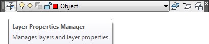
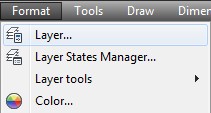
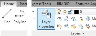
AutoCAD Command: LAYER
The LAYER command is used to open the Layer Property Manager window.
Shortcut: LA
WORKALONG: Working with Layers
Step 1
Using the NEW command, start a new drawing using the template: 2D English.
Step 2
Save and name the drawing: AutoCAD 2D Workalong 05-1. Save it in the folder: CAD Courses/AutoCAD 2D/Lab Exercises
Step 3
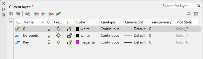
Enter the LAYER command to open the Layer Properties Manager window. (Figure Step 3)
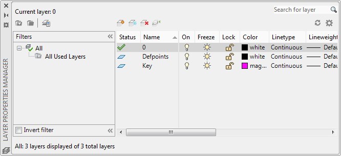
Step 4
Click the small arrow in the upper right of the Filters area to close it. (Figure Step 4)
Step 5
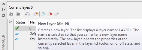
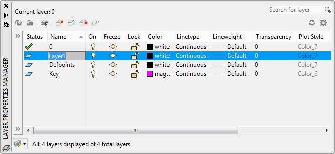
Click the New Layer icon. AutoCAD will create a new layer and automatically name it: Layer1. (Figure Step 5A and 5B)
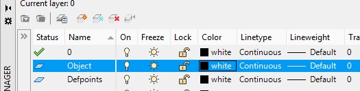
Step 6
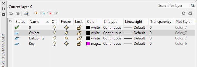
Rename the layer to: Object. (Figure Step 6.)
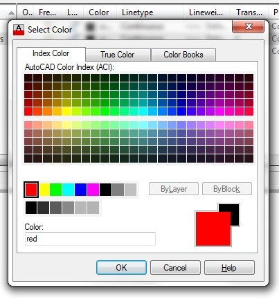
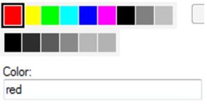
Step 7
Set the color of layer: Object by clicking the color name white. This will open the Select Color dialogue box. Enable the Index Color tab. Select the color red by clicking it or enter the name in the Color box. Click OK to close the dialogue box. (Figure Step 7A and 7B)
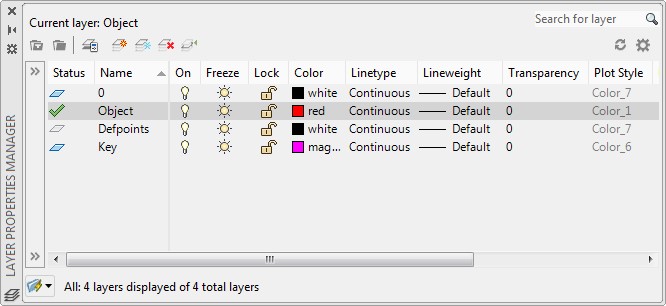
Step 8
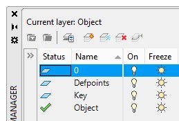
Click layer: Object to highlight it. Click the Set Current icon. (Figure Step 8A and 8B)

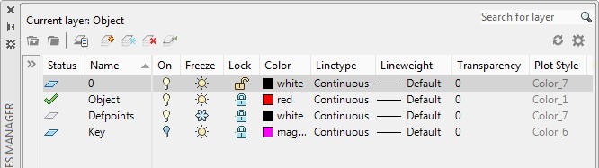
Step 9
Toggle the on/off, thaw/frozen, and lock/unlock properties of the layers by clicking the icons to match the figure. Close the window by clicking the X in the top left corner. (Figure Step 9A and 9B)
Step 10
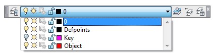
Take note how the current layer will display in the Layer toolbar. In this case, it is Object. (Figure Step 10)

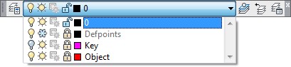
Step 11
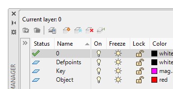
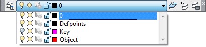
Pull down the layer list by clicking the small triangle on the right side. Change the current layer to 0 by clicking the layer name. (Figure Step 11A and 11B)

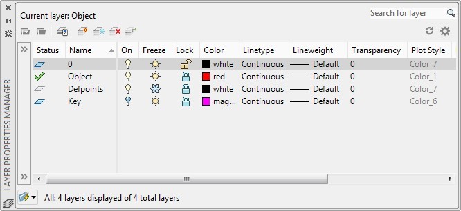
Step 12
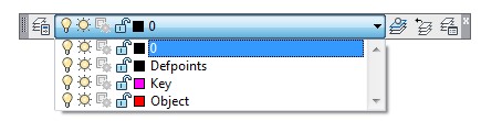
Pull down the layer list again and this time toggle the layer properties so that all four layer are on, thawed, and unlocked. (Figure Step 12)

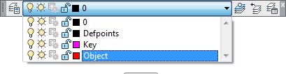
Step 13
Change the current layer to: Object. (Figure Step 13A and 13B)

Step 14
Save and close the drawing.
MUST KNOW: AutoCAD has a special layer named 0 (the number zero). Each new AutoCAD drawing will contain layer 0 . It cannot be deleted or renamed. It has other special attributes as you will see in future modules.
USER TIP: In Module 3, you were shown how to insert a key onto your drawing to check it’s accuracy. The key resides on the layer Key. If you are required to work on your drawing after you inserted the key, toggle layer Key off. To re-check your drawing after you finish the editing, toggle layer Key on as shown in the figures below.
MUST KNOW: The current layer is the layer that any newly created drawing object will reside on. It is important to always be aware of what the current layer is before creating drawing objects. The current layer cannot be frozen.
Key Principles
Key Principles in Module 5
- AutoCAD’s layering system is one of the most important AutoCAD features. Layers allow you to organize, segregate, set the drawing object’s color, control the visibility, and manage plotting of the drawing.
- The current layer is the layer that any newly created drawing object will reside on.
- AutoCAD has a special layer named 0 (the number zero). Each new drawing created in AutoCAD will automatically contain layer 0. It cannot be renamed or deleted.
- A layer that is Off, does NOT display but WILL A layer that is frozen does NOT display and will NOT regenerate.
- The current layer can be turned off but not frozen.
Lab Exercise 5-1
Time allowed: 30 minutes.
| Drawing Name | Template | Units |
|---|---|---|
| AutoCAD 2D Lab 05-1 | 2D English | Inches |
| Layer Name | Objects on Layer | Color |
|---|---|---|
| Object | All lines | Red |
Step 1
Start a new drawing using the template shown above.
Step 2
Save and name the drawing: AutoCAD 2D Lab 05-1. Save it in the folder: CAD Courses/AutoCAD 2D/Lab Exercises.
Step 3
Create a new layer and name it: Object. Set its color red, as shown in the Layering Scheme above.
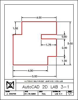
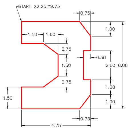
Step 4
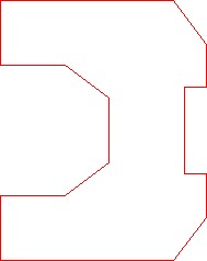
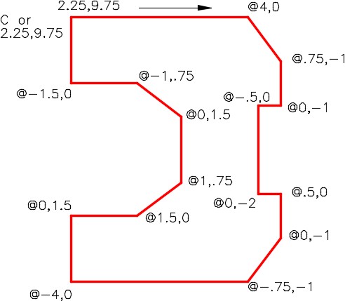
Draw the object shown in the figure. All lines should be on layer: Object and display red. (Figure Step 4A and 4B)
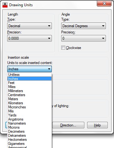
Step 5
Enter the UNITS command. In the Drawing Units dialogue box, set the Insertion Units to Inches. (Figure Step 5)
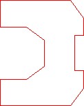
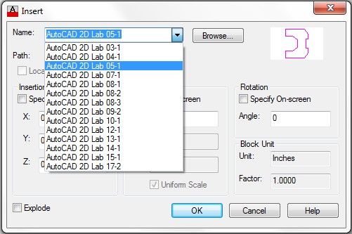
Step 6
Check your drawing with the key. The key name is the same as the drawing name. (Figure Step 6)
Step 7
The drawing should match the figure. (Figure Step 7)

Step 8
Pull down the layer list and turn layer: Key off. (Figure Step 8A and 8B)
Step 9
Pull down the layer list and turn layer Key on. (Figure Step 9A and 9B)

Hint 1
Lab Exercise 5-2
Time allowed: 40 minutes.
| Drawing Name | Template | Units |
|---|---|---|
| AutoCAD 2D Lab 05-2 | 2D Metric | Millimeters |
| Layer Name | Objects on Layer | Color |
|---|---|---|
| Object | All lines | Red |
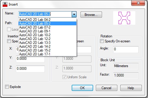
Step 1
Start a new drawing using the template shown above.
Step 2
Save and name the drawing: AutoCAD 2D Lab 05-2. Save it in the folder: CAD Courses/AutoCAD 2D/Lab Exercises.
Step 3
Create the layer: Object, color red, as shown in the Layering Scheme above.
Step 4
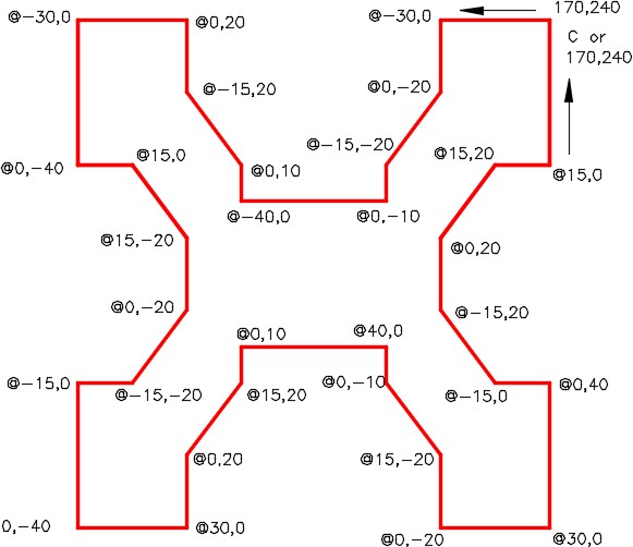
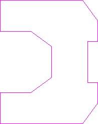
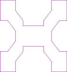
Draw the object shown in the figure. All lines should be on layer: Object and display red. (Figure Step 4A and 4B)
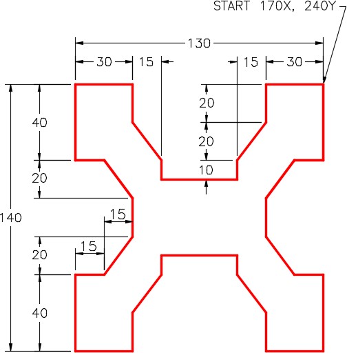
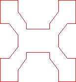
Completed Drawing
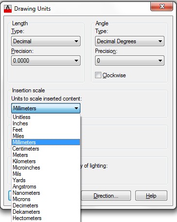
Step 5
Enter the UNITS command. In the Drawing Units dialogue box, set the Insertion Units to Millimeters. (Figure Step 5)
Step 6
Check your drawing with the key. The key name is the same as the drawing name. (Figure Step 6)
Step 7
Your drawing should match the figure. (Figure Step 7)
Step 8
Save and close the drawing.
Hint 1