Module 20: Moving and Copying
Learning Outcomes
When you have completed this module, you will be able to:
- Describe how to move and copy objects in the current drawing and from one drawing to another.
- Apply the MOVE, COPY, COPYCLIP, PASTECLIP, and COPYBASE commands to move and copy objects in the current drawing plus copy objects from one drawing to another.
- Apply the FILETAB and FILETABCLOSE commands to enable the display of the open drawing file tabs above the Graphic window.
- Describe how to construct a tangent arc that has one end tangent to a line and other end going through a point.
- Fill out titleblocks in Paper space using the AutoCAD 2D book Standards.
Moving and Copying Objects
One of the real benefits of using a CAD program is increasing your design and drawing productivity. Using the MOVE and COPY commands are a big part of that productivity. In AutoCAD, objects only have to be drawn once and then they can be used over and over again even if they are in a different drawing or at a different size or orientation. If an object has to be drawn that is similar to one that was previously drawn, simply copy it and change it. Using these principles in the your day-to-day work will noticeably increase your productivity.
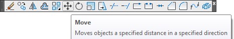
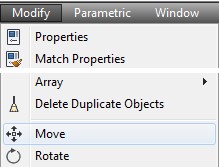
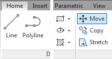
AutoCAD Command: MOVE
The MOVE command is used to move drawing objects from one location to another on the current drawing.
Shortcut: M
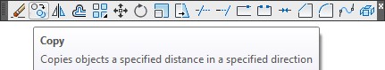
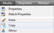
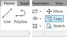
AutoCAD Command: COPY
The COPY command is used to copy existing drawing objects in the current drawing.
Shortcut: CO
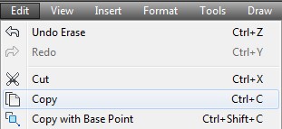
AutoCAD Command: COPYCLIP
The COPYCLIP command is used to copy drawing objects from the current drawing onto the clipboard.
Shortcut: CTRL+C
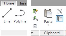
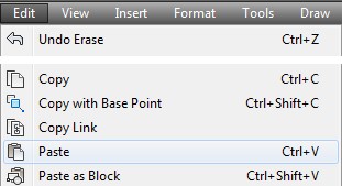
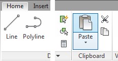
AutoCAD Command: PASTECLIP
The PASTECLIP command is used to paste drawing objects from the clipboard into the current drawing.
Shortcut: CTRL+V
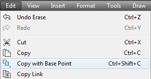
AutoCAD Command: COPYBASE
The COPYBASE command is used to copy drawing objects in the current drawing onto the clipboard with a known basepoint.
Shortcut: CTRL+SHIFT+C
WORKALONG: Moving and Copying Objects
Step 1
Start a new drawing using the template: 2D Layout English.
Step 2
Save and name the drawing: AutoCAD 2D Workalong 20-1.
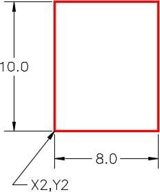
Step 3
On layer: Object, draw the rectangle shown in the figure. (Figure Step 3)
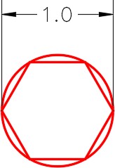
Step 4
On layer: Object, draw a circle and the inscribed hexagon as shown in the figure. Draw it anywhere outside of the rectangle. (Figure Step 4A and 4B)
Step 5 IMPORTANT STEP
Unless otherwise instructed, when starting each lab exercise, while working on workalongs and lab exercises in the AutoCAD 2D book, ensure that all items on the Status bar are disabled. (Figure Step 5)

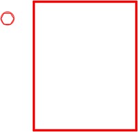
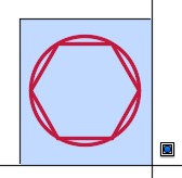
Step 6
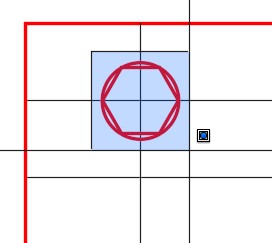
Enter the MOVE command, as shown below, to move the circle and hexagon inside the rectangle to the absolute coordinates X3.5,Y11. (Figure Step 6A, 6B, and 6C)
Command: MOVE
Select objects:
Specify opposite corner:
(Selecting the object using a window.)
Select objects:
(Press Enter)
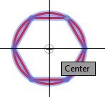
Specify base point or [Displacement] <Displacement>: (cen)
(Snap to the center of the circle.)
Specify second point or <use first point as displacement>: 3.5,11
Command:

Step 7
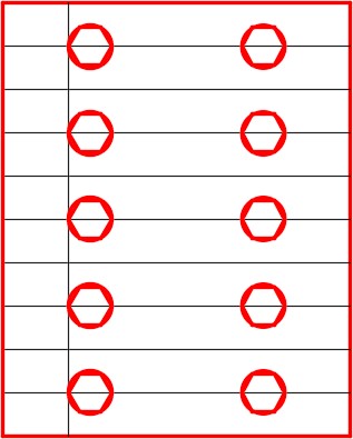
Using the OFFSET command, offset the top line of the rectangle 1 inch down. Change the layer of the line you just created to layer: Construction. (Figure Step 7)

Step 8
Using the OFFSET command, offset the top construction line 8 times at a distance of 1 inch as shown in the figure. (Figure Step 8)

Step 9
Using the OFFSET command, offset the left line of the rectangle 1.5 inches to the right. Change the layer of the line you just created to layer: Construction. (Figure Step 9)

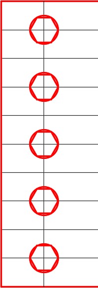
Step 10
Enter the COPY command, as shown below, to copy the circle and hexagon 4 times. (Figure Step 10A, 10B, 10C, and 10D)
Command: COPY
Select objects:
Specify opposite corner: 7 found
(Use a window to select the objects)
Select objects:
Current settings: Copy mode = Multiple
Specify base point or [Displacement/mOde] <Displacement>:
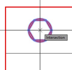
or <use first point as displacement>: (int)
(Snap to the intersection of the lines for the base point)
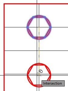
Specify second point or [Exit/Undo] <Exit>: (int)
Specify second point or [Exit/Undo] <Exit>: (int)
Specify second point or [Exit/Undo] <Exit>: (int)
Specify second point or [Exit/Undo] <Exit>: (int)
(Snap to the intersection of the construction lines)
Command:
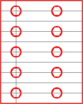
Step 11
Enter the COPY command, as shown below, to copy all circles and hexagons 4 inches in the positive X direction. (Figure Step 11A and 11B)
Command: COPY
Select objects: Specify opposite corner: 35 found
Select objects:
Current settings: Copy mode = Multiple
Specify base point or [Displacement/mOde] <Displacement>: 0,0
(The base point)
Specify second point or <use first point as displacement>: @4,0
(The second point is set 4 inches in the positive X direction.)
Specify second point or [Exit/Undo] <Exit>:
Command:
Step 12
Enter the MOVE command, as shown below, to move all the circles and hexagons 0.5 inches in the positive X direction. (Figure Step 12A and 12B)
Command: MOVE
Select objects:
Specify opposite corner: 70 found
(Use a window to select the objects.)
Select objects:
Specify base point or [Displacement] <Displacement>: 0,0
Specify second point or <use first point as displacement>: @0.5,0
Command:
Step 13
Freeze layer: Construction. (Figure Step 13)
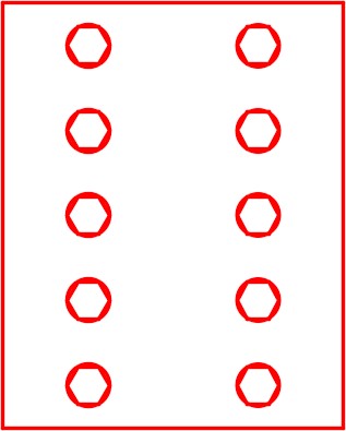
Step 14
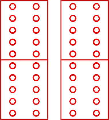
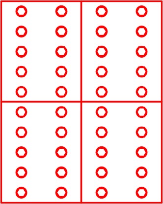
Enter the COPY command, as shown below, to copy all objects. (Figure Step 14A, 14B, and 14C)
Command: COPY
Select objects:
Specify opposite corner: 74 found
(Select all objects using a crossing window.)
Select objects:
Current settings: Copy mode = Multiple
Specify base point or [Displacement/mOde] <Displacement>:
(end)
(Snap to the end of the line.)
Specify second point: (end)
(Snap to the other end of the line.)
Command:
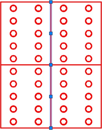
Step 15
Delete the line in the center by picking it and pressing the Delete key. (Figure Step 15)
Step 16
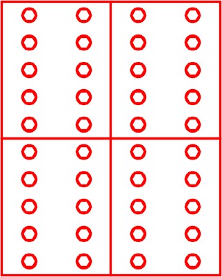
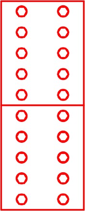
Using what you just learned, copy all of the objects down to match the figure. (Figure Step 16)
Step 17
Delete the lines that were duplicated.
Step 18
Save and close the drawing.
AutoCAD Command: FILETAB
The FILETAB command enables the display of the open drawing file tabs above the Graphic window.
Shortcut: none
AutoCAD Command: FILETABCLOSE
The FILETABCLOSE command disables the display of the open drawing file tabs on top of the Graphic window.
Shortcut: none
WORKALONG: Using the COPYCLIP, PASTECLIP and COPYBASE Commands
Step 1
Start a NEW drawing using the template: 2D Layout English. Save and name the drawing: AutoCAD 2D Workalong 20-2.
Step 2
Using the OPEN command, open the drawing: AutoCAD 2D Workalong 20-1. (Figure Step 2)
Step 3
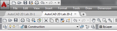
If necessary, enter the FILETAB command to enable the display of the drawing file tabs on top of the Graphic window. You should see two tabs, one for each open drawing. Ensure that the drawing named: AutoCAD 2D Workalong 20-1 is the current drawing as shown in the figure. (Figure Step 3)
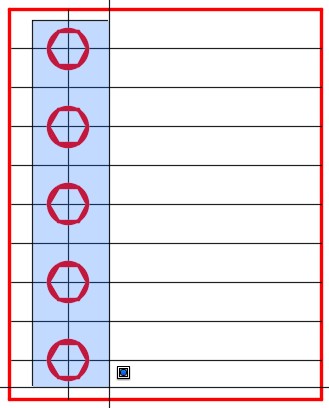
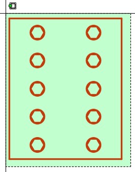
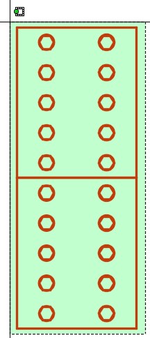
Step 4
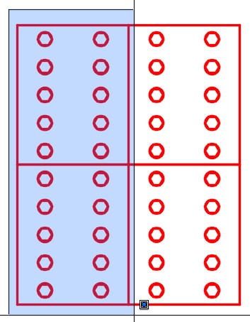
Without entering a command, use a window and select the objects as shown in the figure. (Figure Step 4)
Step 5
Enter the COPYBASE command using the Pull-down menu or by entering in the command as shown below. Enter 0,0 for the base point. (Figure Step 5).
Command: COPYBASE
Specify base point: 0,0
150 found
Command:
Step 6
Click the tab to set the current drawing to: AutoCAD 2D Workalong 20-2. (Figure Step 6)
Step 7
Enter the PASTECLIP command using the Pull-down menu or by entering the command as shown below. Enter 0,0 for the insertion point. (Figure Step 7).
Command: PASTECLIP
Specify insertion point: 0,0
Command:
Step 8
Enter the ZOOM Extents command.
Step 9
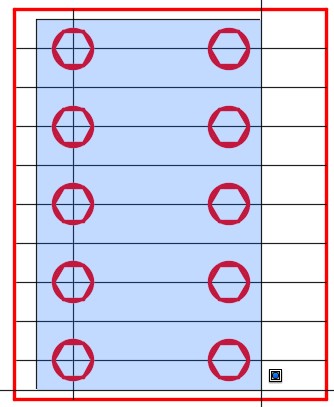
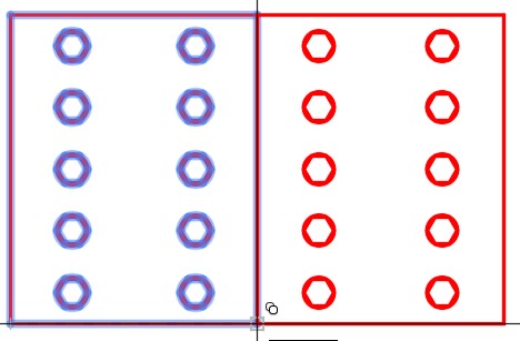
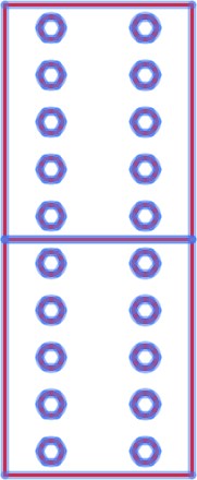
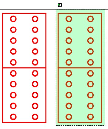
Enter the COPYCLIP command and select all objects using a crossing window. (Figure Step 9A, 9B, and 9C)
Step 10
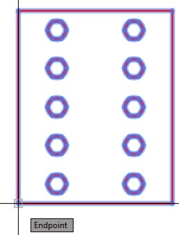
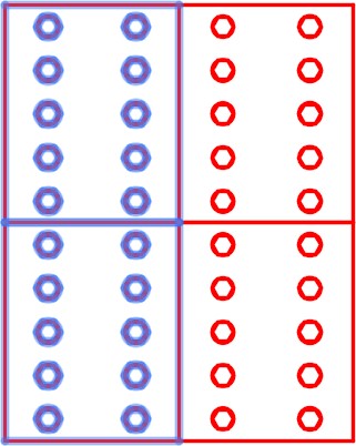
Enter the PASTECLIP command and when prompted for the Insertion point, select anywhere on the drawing. Match the location the best you can as shown in the figure. (Figure Step 10A, and 10B)
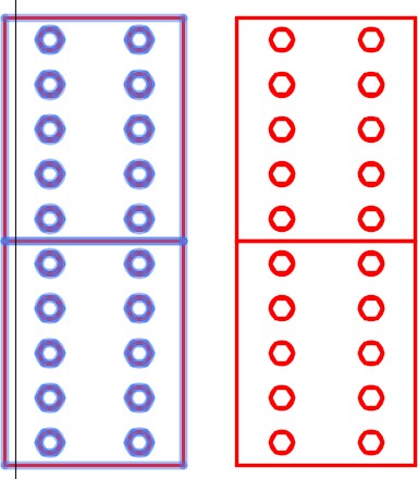
Step 11
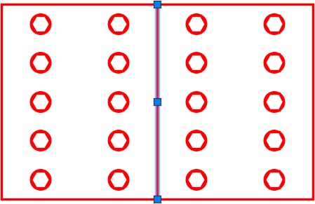
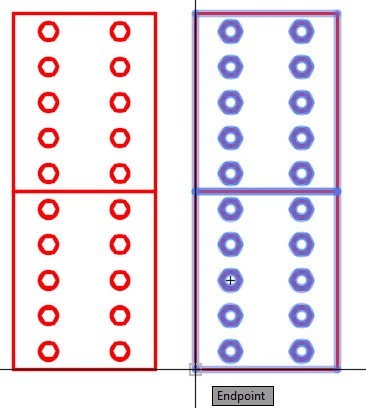
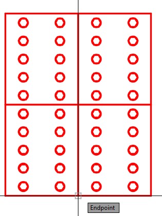
Using what you learned earlier in this module, move the objects on the right and snap the bottom left corner to the bottom right corner of the original objects. (Figure Step 11A, 11B, 11C, and 11D)
Step 12
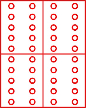
Delete the lines that were duplicated. (Figure step 12)
Step 13
Save and close the drawing.
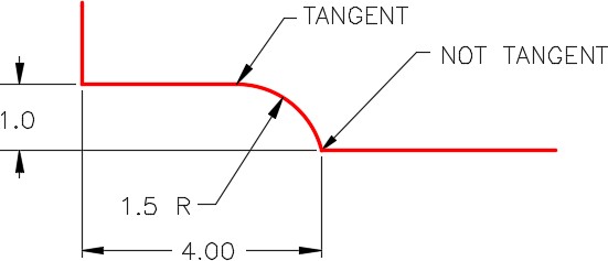
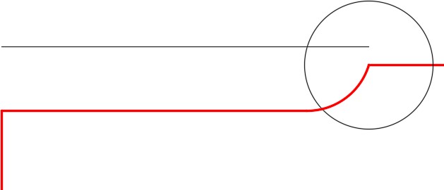
Geometry Lesson: Tangency – Part 2
When an arc must be constructed that has one end tangent to a line and other end going through a point, you cannot use the FILLET command. A fillet MUST be tangent at both ends. It must be drawn as an arc as follows:
Step 1
This is the arc to be drawn. (Figure Step 1)
Step 2
Draw the construction lines. (Figure Step 2)

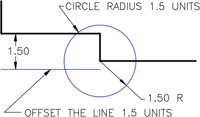
Step 3
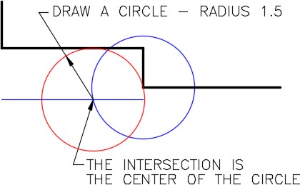
Offset the line which is tangent to the arc at a distance of 1.5 units.1.5 is the radius of the arc being inserted. Draw a circle with the radius of 1.5 units with its center at the point where the arc ends. (Figure Step 3)
Step 4
Draw the circle with a radius of 1.5. Its center is the intersection of the offset line and the circle. (Figure Step 4)
Step 5
Trim the circle you drew in Step 4 and turn layer Construction off. (Figure Step 5)

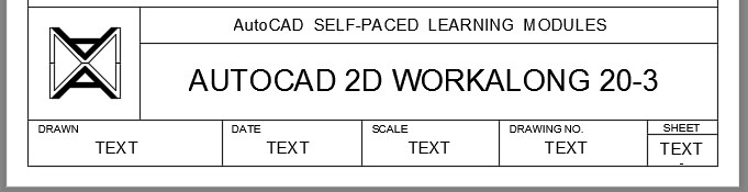
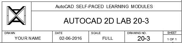
AutoCAD book Standards: Filling in the Titleblock
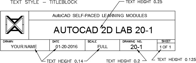
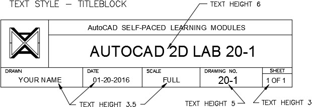
When filling in the titleblock in the workalongs and lab exercises in the AutoCAD 2D book, use the following standards:
- Set Titleblock as the current text style.
- Set layer Titleblock Text as the current layer.
- Use a text height that matches the area being filling. You can pick a text height to use that looks pleasing to your eye. See the figures below for approximate text heights.
- Center the text by eye. It helps to use middle justified. Use the MOVE and ORTHO commands to make the job easier.
- Fill in the bottom row with your actual name, the actual date, scale, drawing number, and sheet number.
- The format of the date is: Month-Day-Year, MM-DD-YYYY For example: 01-20-2014 (For January 20, 2014)
WORKALONG: Construction Techniques
Step 1
Start a new drawing using the template: 2D Layout English.
Step 2
Save and name the drawing: AutoCAD 2D Workalong 20-3.
Step 3
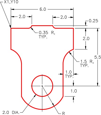
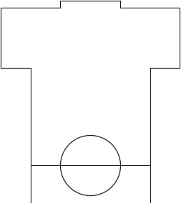
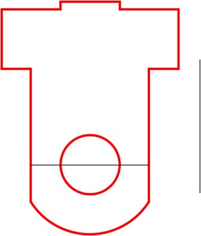
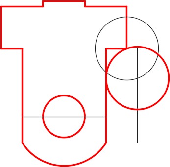
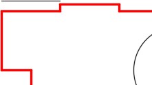
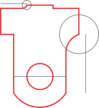
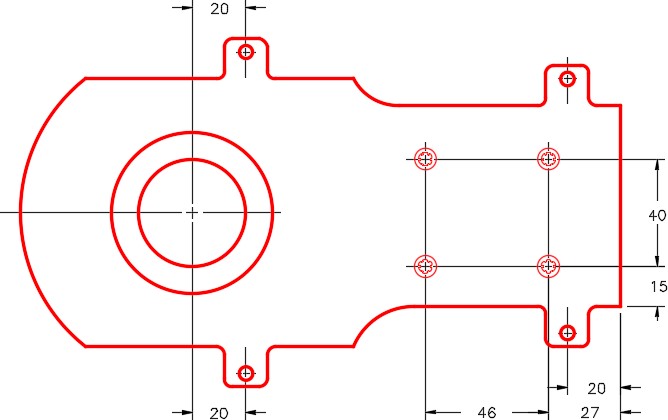
Set layer: Construction as the current layer. Using the dimensioned drawing as a reference, draw the lines and circle to match the figure. (Figure Step 3A and 3B)
Step 4
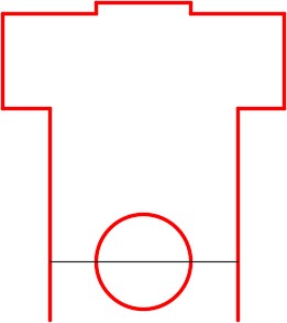
Change the layer of the object lines and the circle to layer: Object. (Figure Step 4)
Step 5
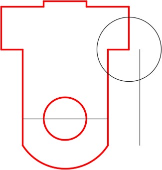
Draw a circle snapping its center location to the center of the circle and snap to the end of the line to specify the radius. Trim the circle. (Figure Step 5A and 5B)
Step 6
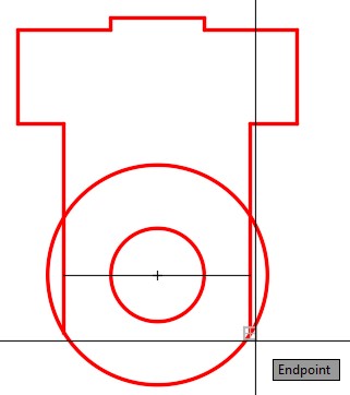
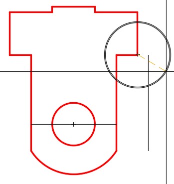
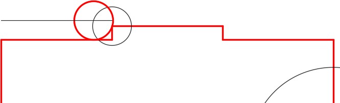
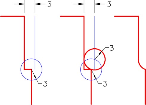
Offset the line, 1.5 inches, on the right side. Change the layer of the line to layer: Construction. On layer: Construction, draw a circle with a 1.5 radius and snap its center to the end of the line as shown in the figure. (Figure Step 6A, 6B, and 6C)
Step 7
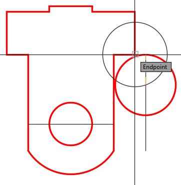
On layer: Object, draw a circle by snapping its center to the intersection of the construction circle and offset line. Show AutoCAD the radius, of 1.5, by snapping to the end of the line. (Figure Step 7A and 7B)
Step 8
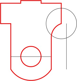
Trim the circle first. Delete one line and trim the other line. (Figure Step 8)
Step 9
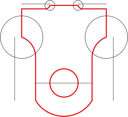
Offset the line on the top 0.35 inches. Change the layer of the line to layer: Construction. On layer: Construction, draw a circle with a 0.35 inch radius. Snap its center to the end of the line as shown in the figure. (Figure Step 9A and 9B)

Step 10
On layer: Object, draw a circle by snapping its center to the intersection of the construction circle and construction line. Show AutoCAD the radius, of 0.35, by snapping to the end of the line as shown in the figure. (Figure Step 10)
Step 11
Delete one line and trim the other line. Trim the circle that you drew in Step 10. (Figure Step 11)
Step 12
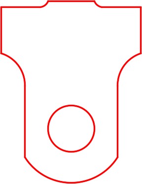
Your drawing should match the figure. (Figure Step 12)
Step 13
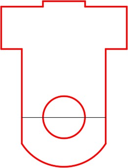
Using what you just learned, draw the arcs on the opposite sides. (Figure Step 13)
Step 14
Turn layer: Construction off. Your completed object should match the figure. (Figure Step 14)
Step 15
Enable layout: Module Layout A. (Figure Step 15)
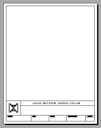
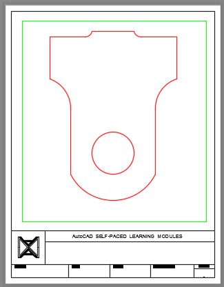
Step 16
On layer: Viewport, use the MVIEW command and create a viewport as shown in the figure. Switch to Model space and enter the ZOOM Extents command. (Figure Step 16)
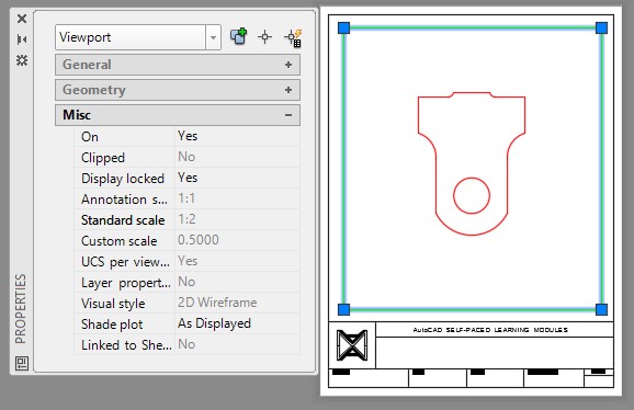
Step 17
With paper space as working space, open the Properties window. Select the viewport and set the Standard scale to 1:2 and lock its display. (Figure Step 17)
Step 18
Turn layer: Viewport off. (Figure Step 18)
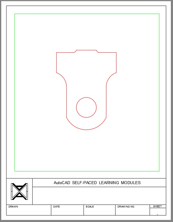
Step 19
Set layer: Titleblock Text as the current layer and set the current text style: Titleblock. Zoom in on the titleblock. (Figure Step 19)
Step 20
With the Paper space the current space, enter the DTEXT command and insert the drawing title text at a height of 0.25 using middle justified. Select a location by eye. It does not have to be placed exactly as you will be moving it later. (Figure Step 20)
Step 21
Using the MOVE command, move the text locating it by eye to center it horizontally and vertically. (Figure Step 21)
Step 22
Enter the DTEXT command enter the text TEXT at a height of 0.14. Center it by eye using the MOVE command. (Figure Step 22)
Step 23
Use the COPY command and Ortho mode, copy the text to the next two locations. Disable Ortho mode and copy the text into the two locations on the right and center the text by eye. (Figure Step 23)
Step 24
Use the text editor to edit the text. (Figure Step 24)
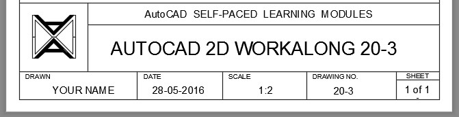
Step 25
If required, change the text height to match the standards under “AutoCAD book Standards: Filling in the Titleblock”. (Figure Step 25)
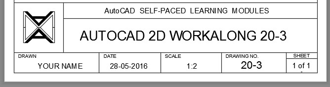
Step 26
Your completed drawing should the figure. (Figure Step 26)
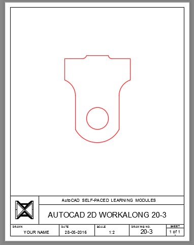
Step 27
Save and close the drawing.
USER TIP: The FILETAB command enables the display of the drawing file tabs on top of the Graphic window and the FILETABCLOSE disables the display.
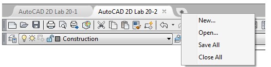
 If you click the small arrow at the end of the tab, a handy menu displays as shown below.
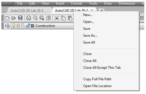
 If you right click on a tab, a handy menu displays as shown below.
Key Principles
Key Principles in Module 20
- Objects only have to be drawn once in AutoCAD and then they can be used over and over again even if they are in a different drawing or at a different size or orientation.
- When an object is copied, the copies retain all of the properties of the original object.
- When copying objects from one drawing to another and the objects must be in the exact location as the original drawing, use the COPYBASE command with 0,0 as the base point. Use the same coordinates when pasting it into the new drawing.
Lab Exercise 20-1
Time allowed: 60 minutes.
| Drawing Name | Template | Units |
|---|---|---|
| AutoCAD 2D Lab 20-1 | 2D Layout English | Inches |
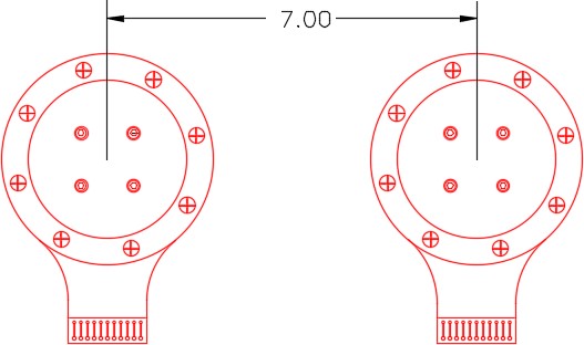
Step 1
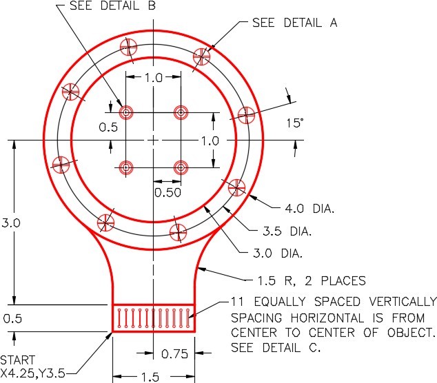
On layer Object, draw the object shown in the figure. (Figure Step 1A. 1B, and 1C)
Step 2
Draw all construction objects on layer: Construction.
Step 3
Set the insertion units and insert the key. Check the drawing for accuracy.
Step 4
Turn layer: Key off and freeze layer: Construction.

Completed Drawing
Step 5
Copy all of the objects 7 units in the X direction to complete the drawing. (Figure Step 5)
Lab Exercise 20-2
Time allowed: 45 minutes.
| Drawing Name | Template | Units |
|---|---|---|
| AutoCAD 2D Lab 20-2 | 2D Layout Metric | Millimeters |
Step 1
On layer Object, draw the object shown in the figure. (Figure Step 1A, 1B, and 1C)
Step 2
Draw all construction objects on layer: Construction.
Step 3
Set the insertion units and insert the key. Check the drawing for accuracy.
Step 4
Turn layer: Key off and freeze layer: Construction.
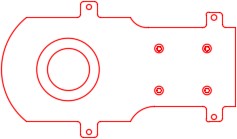
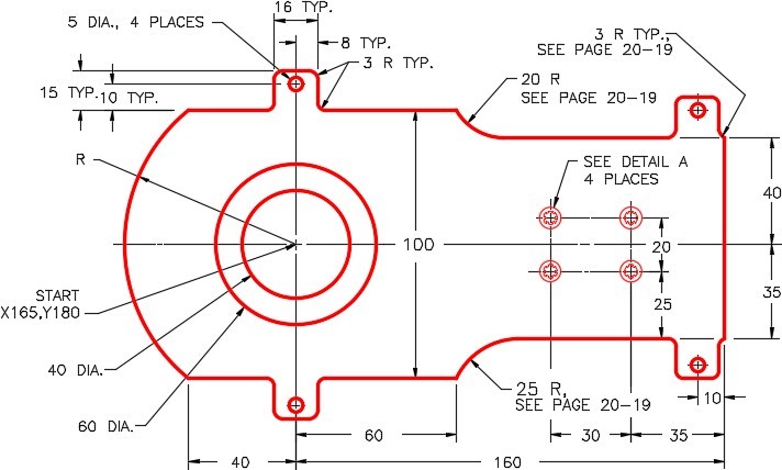
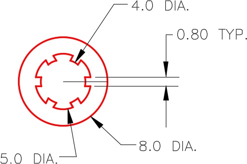
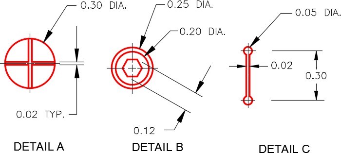
Figure Step 1C
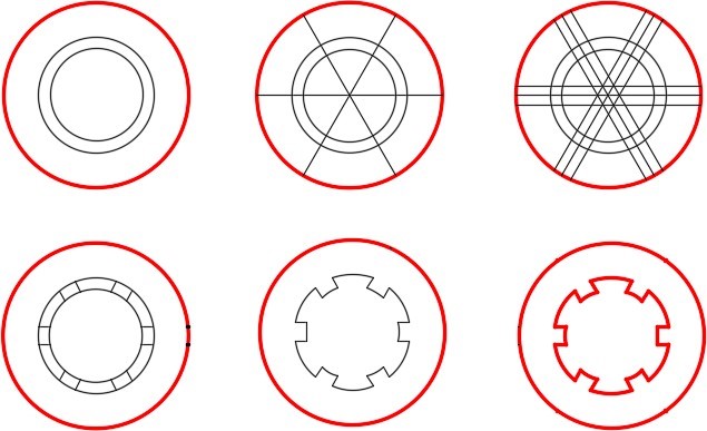
Hint 1
Construct the object in Detail A using the following 6 steps. (Figure Hint 1)
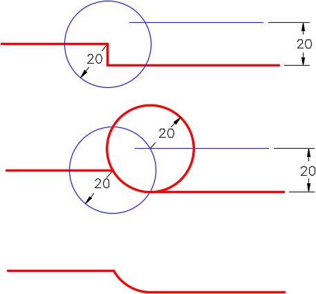
Hint 2
There are four locations on the object that you must use the Geometry Lesson on Tangency. Figure Hint 2A and 2B shows you the three steps to draw two of them. (Figure Hint 2A and 2B)
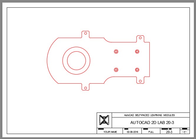
Lab Exercise 20-3
Time allowed: 30 minutes.
| Drawing Name | Template | Units |
|---|---|---|
| AutoCAD 2D Lab 20-3 | 2D Layout Metric | Millimeters |
Step 1
Start a new drawing using the information above. Save and name the drawing: AutoCAD 2D Lab 20-3.
Step 2
Open drawing: AutoCAD 2D Lab 20-2. There should now be two drawings open.
Step 3
Using the COPYBASE and PASTECLIP commands, copy all of the objects from drawing Lab 20-2 into drawing Lab 20-3. Use the basepoint 0,0.
Step 4
Close drawing: AutoCAD 2D Lab 20-2.
Step 5
Edit the drawing: AutoCAD 2D Lab 20-3 to match the figure. Use the MOVE and COPY commands wherever possible. (Figure Step 5A and 5B)
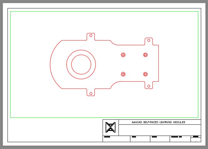
Completed Drawing
Step 6
Enable layout: Module Layout A3. On layer Viewport, use the MVIEW command and create a viewport as shown in the figure. Set the scale of the viewport to 1:1 and lock the display. (Figure Step 6)
Step 7
Using the standards under “AutoCAD book Standards: Filling in the Titleblock”. (Figure Step 7)
Step 8
Turn layer: Viewport off. (Figure Step 8)