Module 18: Layouts – Part 1
Learning Outcomes
When you have completed this module, you will be able to:
- Describe Model space and Paper space and explain how they are used in AutoCAD.
- Describe a Layout and explain how they are used in an AutoCAD drawing.
- Apply the MSPACE and PSPACE commands to change the working space.
- Describe a viewport and explain how to create, edit, lock, and set the viewport scale.
- Apply the MVIEW command to create viewports on layout drawings.
Model and Paper Space
Up to this point in the book, you have been drawing Model space. In this module, Paper space and layouts will be introduced. The ideal way to work in AutoCAD is to draw all real objects in Model space and draw all objects that not real, in Paper space.
Model space is a limitless three-dimensional space where the real objects of the model are drawn. For example, if you are drawing a house, everything that is part of the house such as the walls, windows, doors, etc. are drawn in Model space. All parts of the house would be drawn at full scale or full size, exactly as they exist in real life.
Paper space is a virtual two-dimensional space where all objects that are related to the plotted piece of paper, called a layout, are drawn. Objects drawn in Paper space are things like the titleblock, border, dimensions, notes, labels, and bills of material. Paper space is also drawn at full size but the units are the same units as the paper, such as inches or millimeters. The Model space units and the Paper space units do not have to be the same in a drawing.
Layouts
A layout represents a sheet of paper on which one or more scaled views of the model is created complete with such thing as dimensions, notes, border, and titleblock. Layouts are drawn in Paper space. They are an important and essential AutoCAD feature and should be used to plot all AutoCAD drawings.
As many layouts as required can be created in a drawing. The AutoCAD 2D book supplies pre- drawn layouts in two template files named ‘ 2D Layout English.dwt ‘ and ‘ 2D Layout Metric.dwt ‘. You can create your own layouts and save them in a drawing or template file. Creating your own templates is taught in the AutoCAD 2D Advanced book.
Model and Layout Tabs
The Model and Layout tabs are located along the bottom of the Graphic window as shown in Figure 18-1 and 18-2. There is only one Model tab in each drawing but there can be an unlimited number of Layout tabs. You can create your own layouts tabs. This taught in the AutoCAD 2D Advanced book.

Model – Enabled

Module Layout A Layout – Enabled
When the Model tab is enabled, all drawing objects drawn by you will be Model space objects and exist in Model space. When one of the Layout tabs is enabled, as shown in Figure 18-2, the layout drawing will be displayed. In a Layout tab, you can work in either Paper space or Model space.
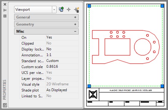
The Working Space
The current space, which is either Model or Paper, is called the working space. When the MODEL icon is enabled, the working space is Model and when the PAPER icon is enabled, the working space is Paper.
When a Layout tab is enabled, the working space can be changed back and forth between Model or Paper space by toggling the PAPER/MODEL icon in the Status bar. See Figures 18-3 and 18-4. Click the MODEL icon to change the working space to Paper space or click the PAPER icon to change the working space to Model space.
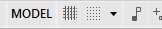
Model Space is Currently the Working Space

Paper Space is Currently the Working Space
The Paper Space Icon
When a Layout tab is enabled and the working space is Paper, the Paper space icon, as shown in Figure 18-5, will display. When the icon is displayed, it is indicating to you that Paper space is the working space and all objects drawn will be Paper space objects and exist in Paper space only.
If this icon does not display, even when a layout is displayed, all objects drawn will be Model space objects and exist in Model space only.

AutoCAD Command: MSPACE
The MSPACE command is used to change the current working space to Model space.
Shortcut: MS
AutoCAD Command: PSPACE
The PSPACE command is used to change the current working space to Paper space.
Shortcut: PS
Viewports
A viewport is a rectangular or square hole cut through the sheet of drawing paper (the layout) so that the model can be viewed through it. See Figure 18-6. It is a 2D Paper space drawing object. The view of the model can be orientated and scaled. A layout can have an unlimited number of viewports cut through it, all viewing the same model at different scales and orientations.
Each viewport will display all visible objects that exist in Model space. If the model is changed after a viewport is created, the viewport will automatically display the changes since it is merely viewing the model. The orientation and scale of a viewport can be adjusted at any time. After a viewport is set, the display can be locked so that it cannot be accidentally changed. If changes are required, the viewport display must be unlocked before they can be made. It is best to insert the viewport on its own layer and turn that layer off before the drawing is plotted to avoid plotting the viewport drawing object.
Paper space objects like dimensions, notes, titleblocks, borders, and text are then drawn in Paper space on the sheet of paper. They are drawn full size using the same units as the paper is measured.
A Viewport
AutoCAD Command: MVIEW
The MVIEW command is used to create a viewport on a layout. It is a Paper space command and the viewport it creates is a Paper space drawing object.
Shortcut: MV
WORKALONG: Working With Layouts
Step 1
Start a new drawing using the template: 2D Layout English.
Step 2
Save and name the drawing: AutoCAD 2D Workalong 18-1.
Step 3
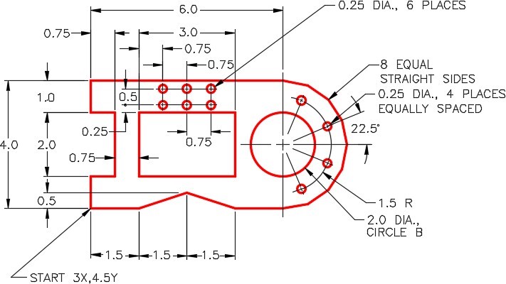
Using what you learned to this point in the book, draw the object shown in the figure on layer: Object. Draw any construction objects on layer: Construction. (Figure Step 3)
Step 4
Freeze layer: Construction. The drawing should appears as shown in the figure. (Figure Step 4)

Step 5
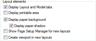
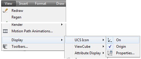
Enter the OPTIONS command to open the Options dialogue box. In the Display tab, compare the settings in the Layout elements area and change them, if necessary, to match the figure. Click OK to close the dialogue box. (Figure Step 5)
Step 6
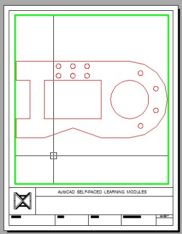
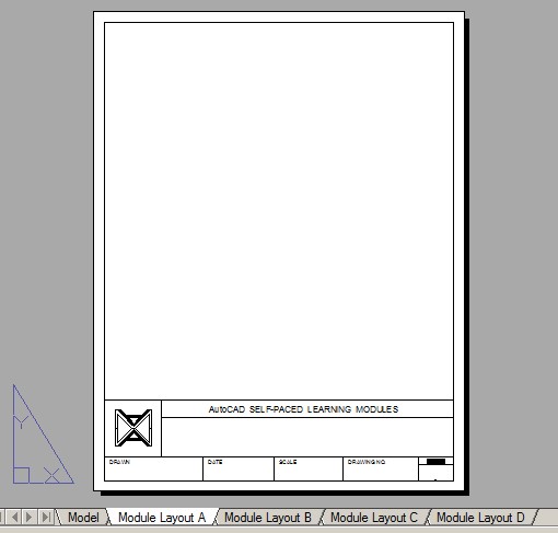
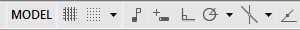
Enable layout: Module Layout A by clicking it. Your Graphic window should match the figure. (Figure Step 6)
Step 7
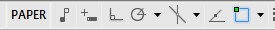
Paper space should be the working space. To check that, ensure that the PAPER icon is enabled on the Status bar. (Figure Step 7)
Step 8
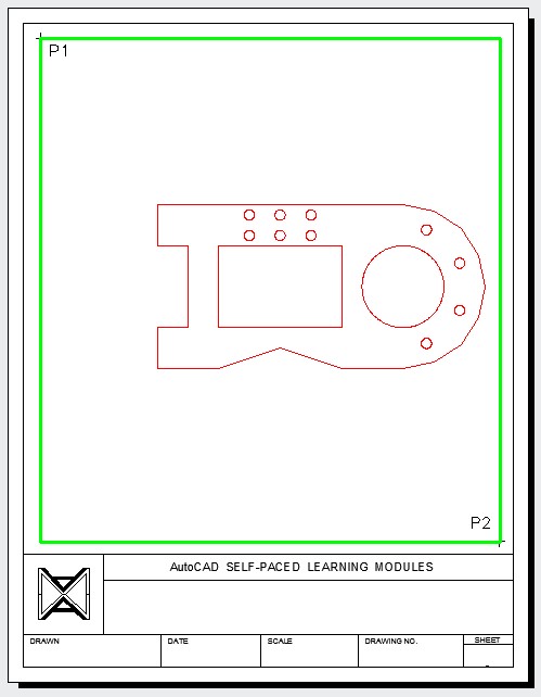
Set layer: Viewport as the current layer. Enter the MVIEW command, as shown below, to create a viewport on the layout. (Figure Step 8)
Command: MVIEW
Specify corner of viewport or [ON/OFF/Fit/Shadeplot/Lock/Object/Polygonal/Restore/LAyer/2/3/4] <Fit>: P1
Specify opposite corner: P2
Command:
Step 9
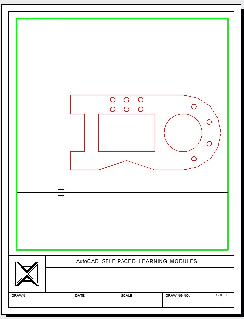
Change the working space to Model by clicking the PAPER icon on the Status bar. After you do that, it will display MODEL as shown in the figure. (Figure Step 9A and 9B)
Step 10
Enter the ZOOM Extents command to display all model objects in the viewport. (Figure Step 10)

Step 11
Change the working space to Paper space. (Figure Step 11)
Step 12
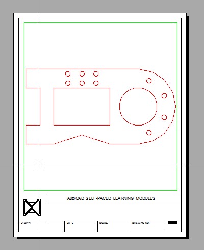
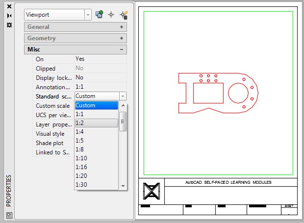
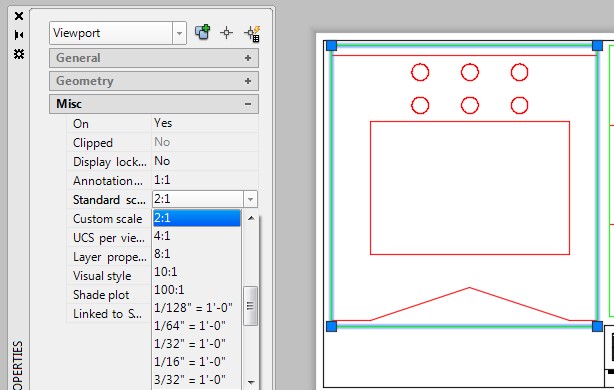
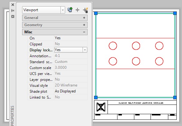
Open the Properties window. Without entering a command, select the viewport. It will highlight, as shown in the figure, and grips will display on the four corners. While the viewport is selected, pull down the Standard scale property and set it to 1:2. (Figure Step 12A and 12B)
Step 13
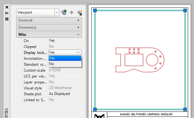
While the viewport is selected, pull down the Display locked property and set it to Yes. (Figure Step 13)
Step 14
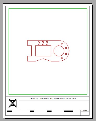
Your completed layout should appear as shown in the figure. (Figure Step 14)
Step 15
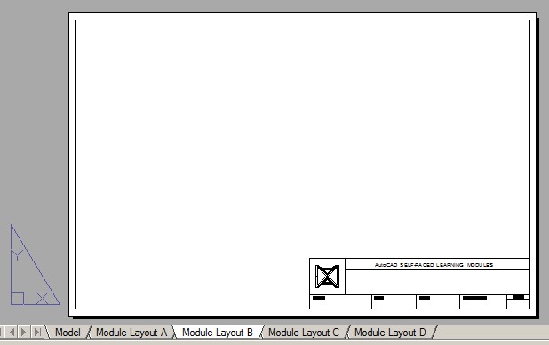
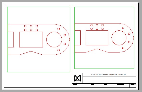
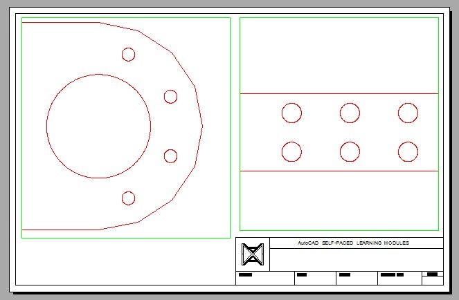
Enable the display of layout: Module Layout B. (Figure Step 15)
Step 16
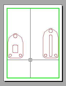
Using what was taught in Step 8, enter the MVIEW command, two times, to create two viewports. After creating the viewports, change the working space to Model and click inside the left viewport. Enter the ZOOM Extents command. Click inside the viewport on the right and enter the ZOOM Extents command again. Change the working space to Paper and the layout should appear similar to the figure. (Figure Step 16)\
Step 17
Using what was taught earlier in the workalong, select the viewport on the left and set the scale to 2:1. (Figure Step17)
Step 18
Change the working space to Model and click inside viewport on the left. (Figure Step 18)
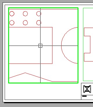
Step 19
Without changing the zoom, pan of the model as shown in the figure. Change to Paper space. (Figure Step 19)
Step 20
Using what was taught earlier in the workalong, use the Properties window and check to ensure that the scale is still set to 2:1. Lock the display. (Figure Step 20)

Step 21
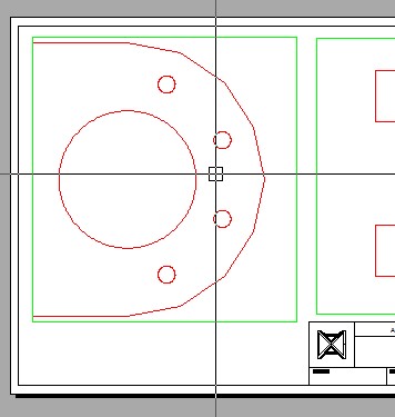
Using what was taught earlier in the workalong, zoom and pan the model in the right viewport. Set the Custom scale to 3 and lock the display. (Figure Step 21A and 21B)

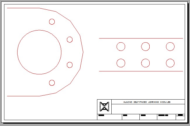
Step 22
Turn layer: Viewport off. Your layout should appears as shown in the figure. (Figure Step 22)
Step 23
Save and close the drawing.
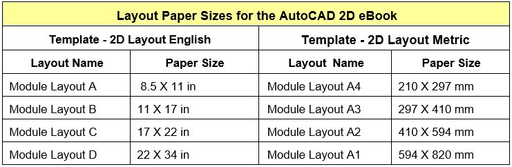
Layout Paper Sizes
MUST KNOW: After you use the MVIEW command to create a viewport in the layout, you should always execute the ZOOM Extents command immediately after. Before you enter the ZOOM Extents command, change the working space to Model. After executing the command, you will be able to see all the visible model objects in the viewport. You can then zoom and pan the model to set the desired view.
Key Principles
Key Principles in Module 18
- Model space is a limitless three-dimensional space where the real objects of the model are drawn.
- Paper space is a virtual two-dimensional space where all objects related to the piece of paper, called a layout, are drawn. Objects drawn in Paper space are things like the titleblock, border, dimensions, notes, labels, and bills of material.
- A viewport is a rectangular or square hole cut through a sheet of drawing paper (layout) so that the model can be viewed at a specified scale and orientation.
- The current space, which is either Model or Paper, is called the working space. Objects drawn in Model space are model space drawing objects and objects drawn in Paper space are paper space drawing objects.
Lab Exercise 18-1
Time allowed: 40 minutes.
| Drawing Name | Template | Units |
|---|---|---|
| AutoCAD 2D Lab 18-1 | 2D Metric | Millimeters |
| Layer Name | Objects on Layer | Color |
|---|---|---|
| Gasket | All objects | Red |
Step 1
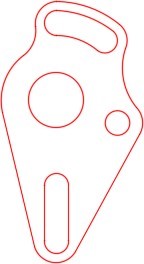
Draw the top view of the gasket shown in the figure using the layering scheme. (Figure Step 1A, 1B, and 1C)
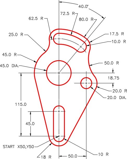
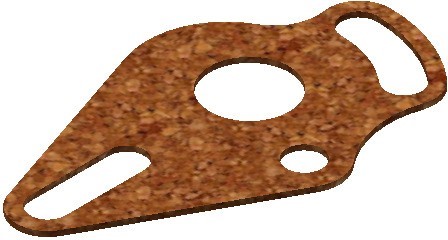
Gasket
Step 2
Set the insertion units and check your drawing with the key. Turn layer: Key off and freeze layer: Construction.
Step 3
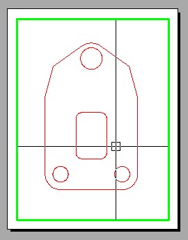
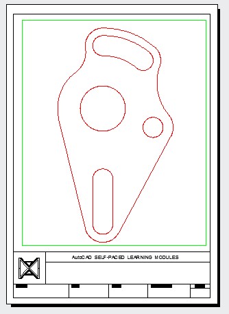
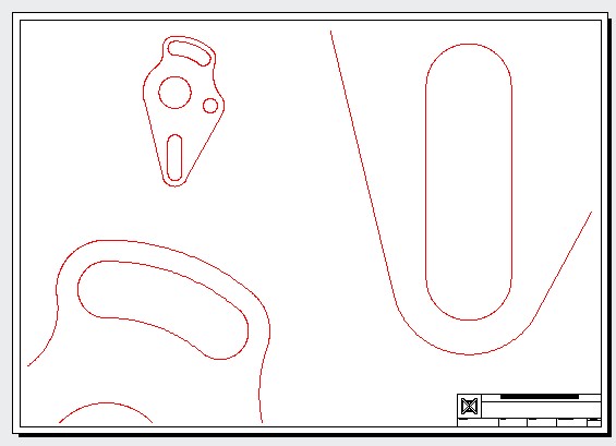
In layout: Module Layout A4, on layer: Viewport, create a viewport using the MVIEW command. Pan the model as shown in the figure. Set the scale to 1:1 and lock the display. (Figure Step 3)
Step 4
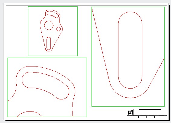
In layout: Module Layout A1, on layer Viewport, create three viewports using the MVIEW command. Pan the model as shown in the figure and set the custom scale of the top left viewport to 1:1, the bottom left viewport to 4:1, and the one on the right to 6:1. Lock the display of all three viewports. (Figure Step 4)
Step 5
Turn layer: Viewport off. (Figure Step 5)
AUTHOR’S HINTS: When you are setting the viewport scale and a standard scale is not available to you, simply type in the scale number in the Custom scale property as shown in the figure below. In this example the scale of 6:1 is entered as 6. If the scale you want to enter is 1:4, then you enter 0.25 (1 divided by 4). Setting custom scale is taught in a future module aand creating standard scales is taught in the AutoCAD 2D Advanced book.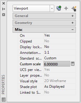
Lab Exercise 18-2
Time allowed: 40 minutes.
| Drawing Name | Template | Units |
|---|---|---|
| AutoCAD 2D Lab 18-2 | 2D Metric | Millimeters |
| Layer Name | Objects on Layer | Color |
|---|---|---|
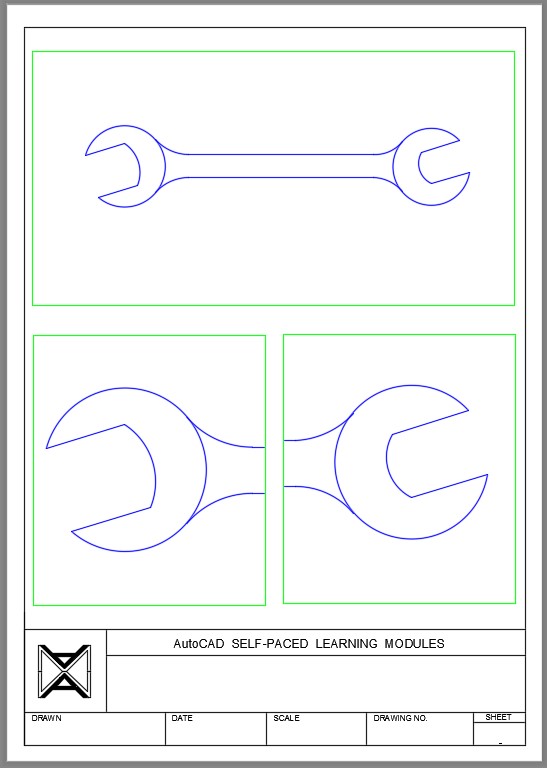
| Wrench | All objects | Blue |
Step 1
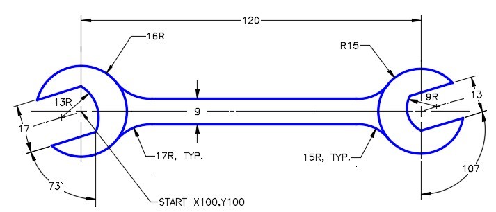
Draw the top view of the wrench shown in the figure using the layering scheme. (Figure Step 1A, 1B, and 1C)

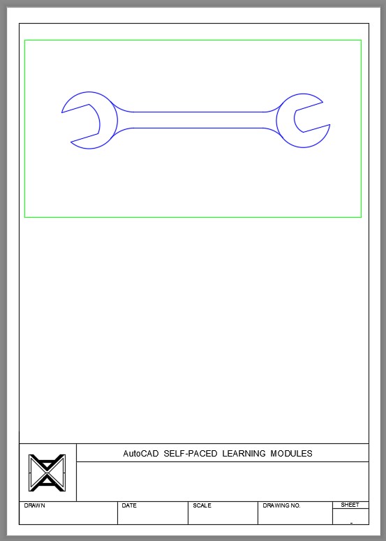
Open End Wrench

Completed Drawing
Step 2
Set the insertion units and check your drawing with the key. Turn layer: Key off and freeze layer: Construction.
Step 3
In layout: Module Layout A4, on layer: Viewport, create a viewport using the MVIEW command. Pan the model as shown in the figure. Set the scale to 1:1 and lock the display. (Figure Step 3)
Step 4
In layout: Module Layout A4, on layer: Viewport, create two additional viewports using the MVIEW command. Pan the model as shown in the figure. Set the scale to 2:1 and lock the display. (Figure Step 4)
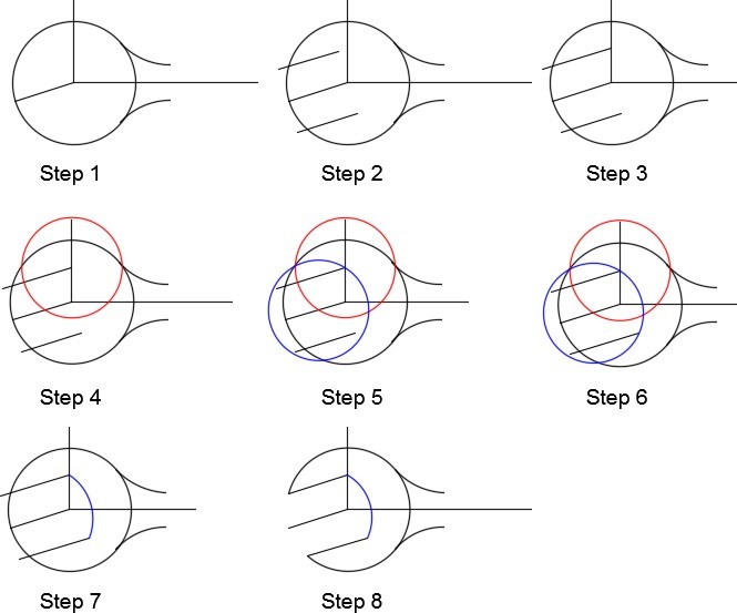
Step 1
Draw the construction lines for the circle and center lines. I am showing only one end in the following figures.
Step 2
Offset the inclined center line on each side. On the left side of the wrench the offset distance is 6.5 mm.
Step 3
Extend the top offset line to the vertical center line.
Step 4
Using the end of the line that you just extended as the center, draw a circle with radius of the small arc. On the left side of the wrench it is 13 mm. I drew it in red to help you identify it.
Step 5
Using the intersection of the circle you just drew and the inclined line as the center, draw a circle with the radius of the small arc. On the left side of the wrench it is 13 mm. I drew it in blue to help you identify it.
Step 6
Extend the bottom offset line to the circle.
Step 7
Trim the blue circle. I removed the red circle to help you. You can leave it in your drawing as a construction line.
Step 8
Finish the trim to complete the left side of the wrench.