Module 40: Layouts – Part 2
Learning Outcomes
When you have completed this module, you will be able to:
- Describe lineweights and their use in a plotted drawing.
- Describe and apply the object and color methods of assigning lineweights in a drawing.
- Explain how to calculate and set customs viewport scakes.
Drafting Lesson: Lineweights
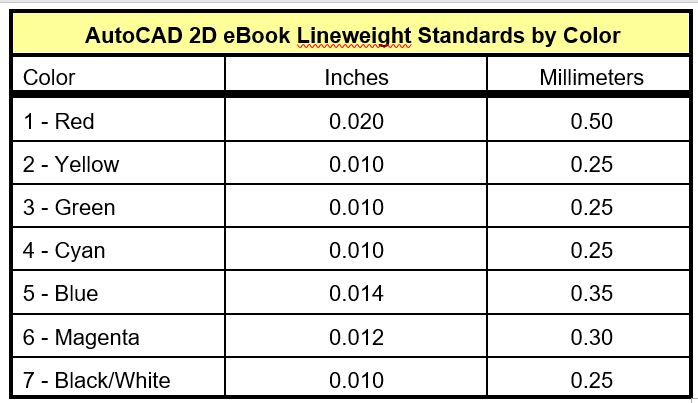
Industry standards have assigned a type, weight, and width to each drawing object on a plotted drawing. This makes the plotted drawings much easier to read and understand. It is important to follow those standards when printing a layout. The AutoCAD 2D book Lineweights chart, Figure 40-1, shows the basic linetypes and their assigned lineweight in both inches and millimeters.
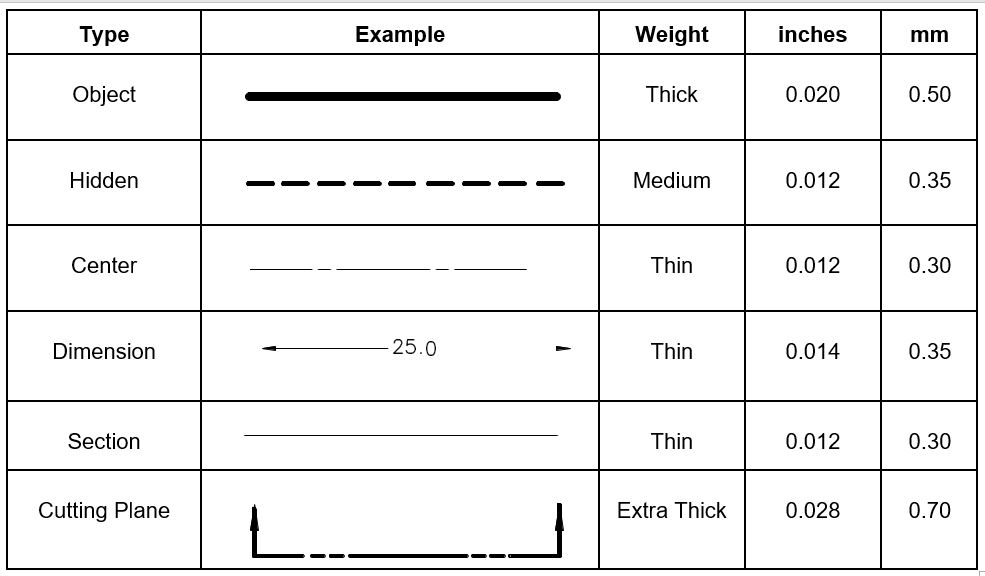
AutoCAD 2D book Lineweight Chart
Lineweights
Assigning and displaying lineweight is not important when creating and editing a drawing, but are very important when the layout of that drawing is printed. Lineweights are normally assigned by a company’s standard. The AutoCAD 2D book Lineweight Chart is shown in Figure 40-1. The two methods of assigning lineweight are by object or by color.
Assigning Lineweights by Object
One method of assigning lineweights is to assign a lineweight to each drawing object. When the layout is plotted, the plotter simply prints the drawing object with its assigned lineweight. When lineweights are assigned using this method, the lineweight can be displayed in both the Graphics window and the paper print. The lineweights can be assigned to each drawing object individually or ByLayer. ByLayer is much easier and is the method practiced in most companies including the AutoCAD 2D book.
Assigning Lineweights by Color
Assigning the lineweight by color is the most popular method used in the CAD world. Using a company standard chart, as shown in Figure 40-1, lineweights are assigned to each color. When the layout is plotted, the plotter looks at the color of each drawing object and prints it with the lineweight assigned to that color. When lineweights are assigned using this method, the lineweight cannot be displayed in the Graphic window. They only appear on the paper print. The color can be assigned ByObject or ByLayer. ByLayer is used by most companies and used in throughout the AutoCAD 2D book.
WORKALONG: Assigning Lineweights
Step 1
Open the drawing: AutoCAD 2D Lab 32-1.
Step 2
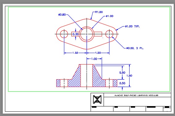
Using the SAVEAS command, save the drawing with the name: AutoCAD 2D Workalong 40-1. (Figure Step 2)
Step 3
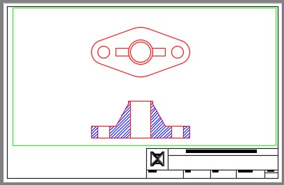
Enable layout: Module Layout B. Create a viewport on layer: Viewport. Set the scale to 1.5:1 and lock the display. (Figure Step 3)
Step 4
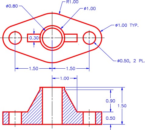
In Paper space, on layer: Center Lines, draw the center lines on the views.
Step 5
Set the current dimensioning style to: 2D English. In Paper space, on layer: Dimensions, insert the dimensions shown on the figure. (Figure step 5A and 5B)
Step 6
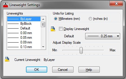
Enter the LINEWEIGHT command to open the Lineweight Settings dialogue box. Ensure that your dialogue box matches the settings in the figure. (Figure Step 6)
Step 7
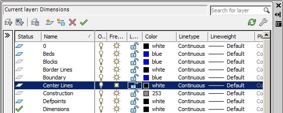
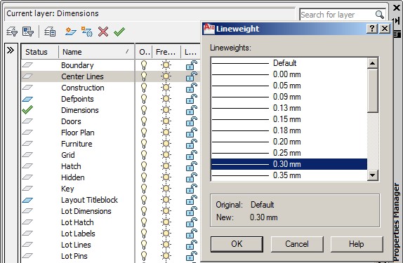
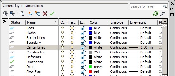
Open the Layer Properties Manager window. Select layer: Center Lines to highlight it. Click Default in the Lineweight column to open the Lineweight dialogue box. Select 0.30 mm. (Figure Step 7A, 7B, and 7C)
Step 8
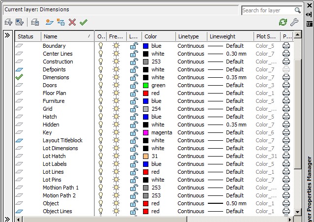
Using what you just learned, change the lineweight of the layers: Dimensions, Hidden, and Object to the lineweights shown in the figure. (Figure Step 8)
Step 9
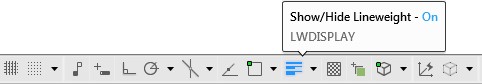
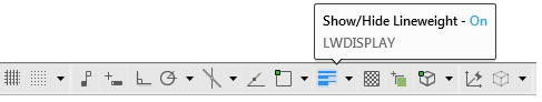
To enable the display of lineweights, enable the LWT icon on the Status bar. (Figure Step 9)
Step 10
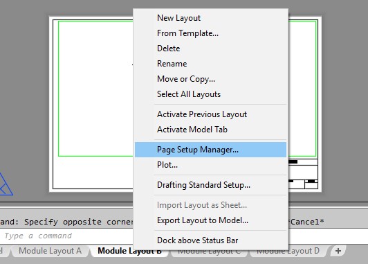
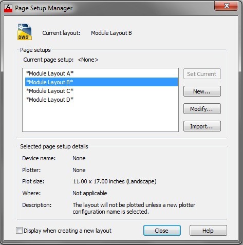
Enable layout: Module Layout B and move the cursor onto the tab for that layout. Right click the mouse. In the Right-click menu, select Page Setup Manager. (Figure Step 10)
Step 11
In the Page Setup Manager dialogue box, select: Module Layout B and then click Modify. (Figure Step 11)
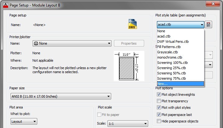
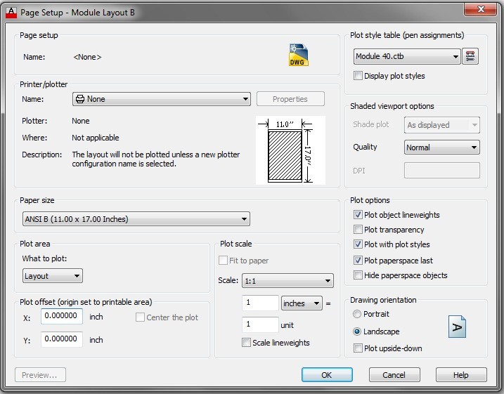
Step 12
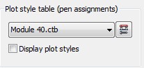
In the Pager Setup – Module Layout B dialogue box, pull down the Plot style table list and click New. (Figure Step 12)
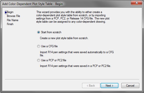
Step 13
In the Add Color Dependent Plot Style Table dialogue box, enable Start from scratch and click Next. (Figure Step 13)
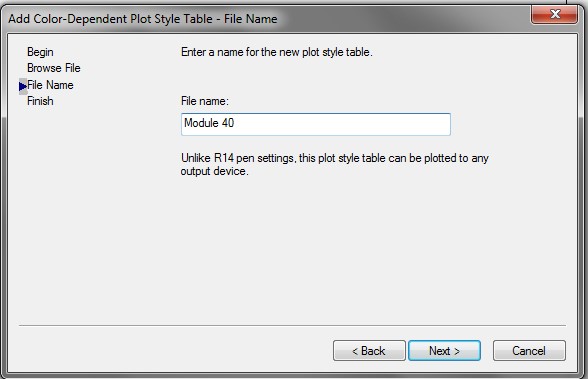
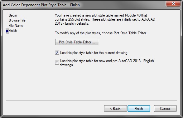
Step 14
Enter the name: Module 40 and click Next. (Figure Step 14)
Step 15
Click the Plot Style Table Editor box. (Figure Step 15)
AutoCAD 2D book Lineweight Standards by Color Chart
Step 16
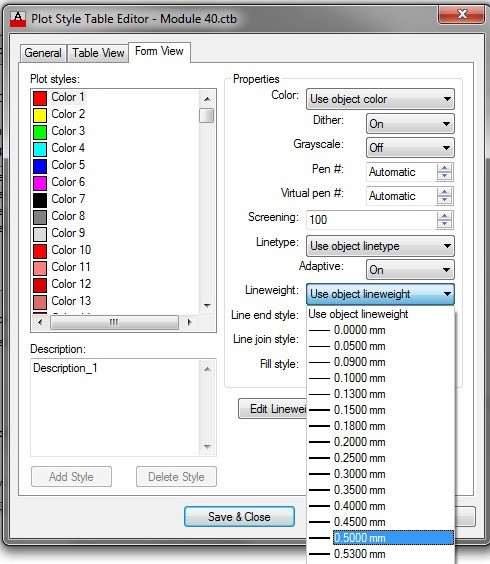
In the Plot styles list, select Color 1 (Red) and then pull down the Lineweight list, select 0.5000 mm. (Figure Step 16)
Step 17
Using the chart shown in Figure 40-2, set the six remaining colors.
Step 18
Click Save & Close. (Figure Step 18)
Step 19
Click OK to close the box.
Step 20
Save and close the drawing.
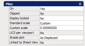
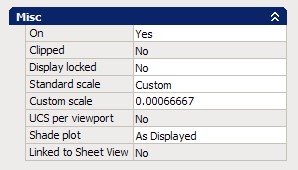
:MUST KNOW: When setting the custom scale property of a viewport, it is important that the length units precision is set to 8 decimal places first using the UNITS command. For example, to set the custom scale of 1:1500, divide 1 by 1500 =0.00066666. To see what could happen if the wrong precision setting is used see below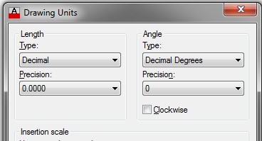
with 8 Decimal Places of Precision
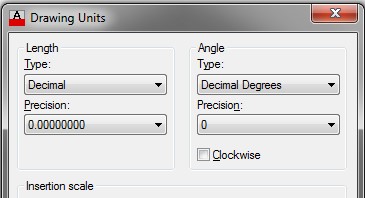
with 8 Decimal Places of Precision
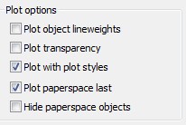
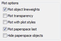
MUST KNOW: Before plotting any layout, the user must choose between plotting it with object lineweights or with a plot style color table. This can be set in the Plot options area in the Page Setup dialogue box. When setting plot by plot style, ensure that the plot style table is set to the desired table.
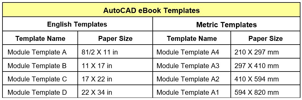
Standard Drawing Paper Sizes
Geometry Lesson: Setting Custom Viewport Scales
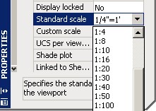
When setting the scale for a viewport and the required scale not listed in the Standard scale property list, you must calculate a custom scale. The custom scale is simple to calculate. It is the scale factor or a ratio of the scale related to 1.
For example, to calculate the scale of:
1/4″ -= 1′-0″
1/4″=1′-0″ or 1/4″=12″ or 1=48 or 1:48
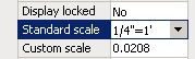
To get the scale factor in decimal format, divide: 1 by 48 = 0.0208
The custom scale would be set at 0.0208
Here are some additional examples:
3/4″ = 1′-0″ or 3/4″=12″ or 48 divided by 3 = 1:16 = 0.0625
| 3/4″=1″ | 1 divided by 0.75 | = 1.33333333 |
| 1:1.5 | 1 divided by 0.75 | = 0.6666666 |
| 1:5 | 1 divided by 5 | = 0.2000000 |
| 1:75 | 1 divided by 75 | = 0.013333333 |
| 1:500 | 1 divided by 500 | = 0.00200000 |
| 1:1500 | 1 divided by 1500 | = 0.00066666 |
| 15:1 | 15 divided by 1 | = 15 |
Key Principles
Key Principles in Module 40
- There are two methods of assigning lineweight to an object. They are lineweight by color and lineweight by object.
- The display of the lineweights assigned to objects in the drawing is enabled or disabled by toggling the LWT icon on the Status bar.
- Before plotting a drawing, choose between plotting it with object lineweights or with a plot style color table.
- When setting the custom scale for a viewport, ensure that the precision is set to 8 decimal places in the Units dialogue box.
