Module 33: Blocks
Learning Outcomes
When you have completed this module, you will be able to:
- Describe a block and explain how blocks are stored and inserted in a drawing file.
- Describe how blocks work with layers.
- Apply the BLOCK and INSERT commands.
- Explain the importance of layer 0 when blocks are created.
Blocks
A block is a collection of drawing objects that acts as one object. After defining a block, it can be inserted into the current drawing as many times as required. It can also be inserted into other drawings or shared with other users. Regardless of the number of times a block has been inserted into the drawing, it will not significantly change the size of the drawing’s database. The EXPLODE command can be used to explode a block back into its individual drawing objects.
Every drawing file has an invisible data area called the block definition table. The block definition table stores all block definitions in that drawing and contains all of the data associated with each block. It is these block definitions that the INSERT command refers to when it is used to insert a block into the drawing. The only way to remove a block from the definition table is to purge it using the PURGE command. All inserted blocks must be deleted before the block definition can be purged from the drawing. Purging is taught in Module 34.
The BLOCK command is used to create a block in the definition table. The INSERT command is used to insert a block, from the definition table, into the drawing. A block can be scaled and/or rotated when it is inserted or it can be scaled and/or rotated after it has been inserted by changing the block’s properties or by using the SCALE and ROTATE commands.
There are two methods available to edit an existing block. The first is to insert the block into the drawing, explode it, and make the necessary changes. After the changes are made, redefine the block and assign the original name. When a block is edited and redefined, it will overwrite the block definition in the block definition table and all insertions of that block will change to appear as the revised block. The second method is to use the BEDIT command. BEDIT is taught in the AutoCAD 2D Advanced book.
Blocks can also have intelligence, called attributes, attached to them. After blocks with assigned attributes are defined and inserted into a drawing, the data attached to them can be extracted.
Attributes and data extraction are taught in the AutoCAD 2D Advanced book.
It is essential to know how blocks and layers work in a drawing. When a block is inserted in a drawing, it will reside on the current layer but it is more important to know what layer the drawing objects, that were used to create the block, were drawn on. See Figure 33-1.
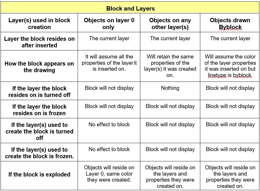
Blocks and Layers
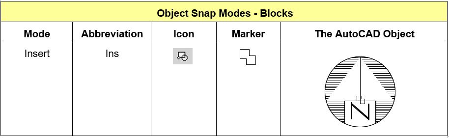
Object Snap Mode – Blocks
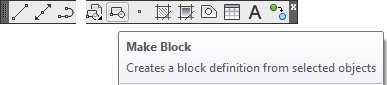
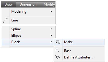
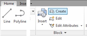
AutoCAD Command: BLOCK
The BLOCK command is used to create a block in the block definition table in the current drawing.
Shortcut: B
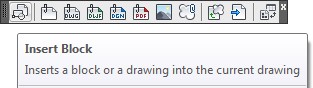
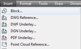
AutoCAD Command: INSERT
The INSERT command is used to insert a block into the current drawing from the current drawings block definition table.
Shortcut: none
WORK ALONG: Creating and Inserting Blocks
Step 1
Start a new drawing using the template: 2D Layout English.
Step 2
Save and name the drawing: AutoCAD 2D Workalong 33-1.
Step 3
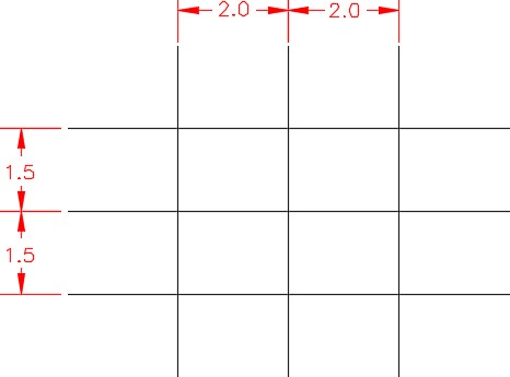
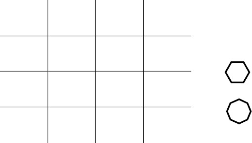
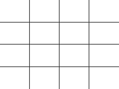
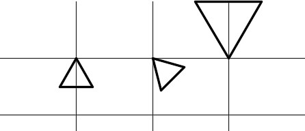
On layer: Construction, draw the three horizontal and 3 vertical lines shown in the dimensioned drawing. Start the first line anywhere in model space. (Figure Step 3)
Step 4
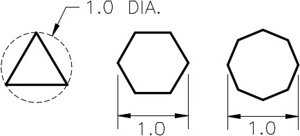
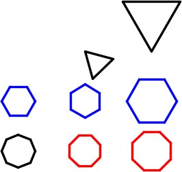
On layer: 0, draw the three polygons as shown in the figure. Draw them anywhere on the drawing. (Figure Step 4A and 4B)
Step 5
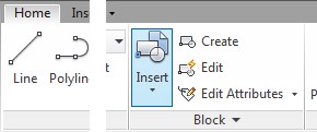
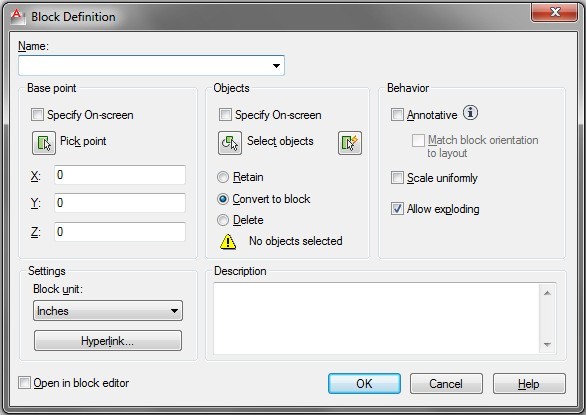
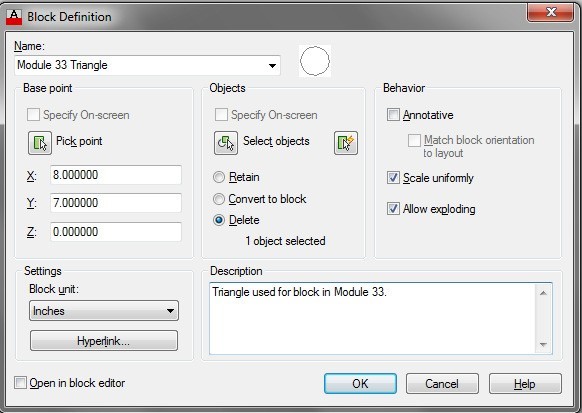
Enter the BLOCK command. It will open the Block Definition dialogue box. (Figure Step 5)
Step 6
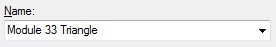
In the Name box, enter the name: Module 33 Triangle for the name of the block. (Figure Step 6)
Step 7
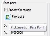
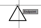
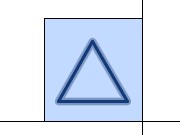
Click the Pick point icon to select the Base point for the block. When prompted for the base point, snap to the top corner of the triangle. (Figure Step 7A and 7B)
Step 8
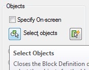
In the Objects area, click the Select objects icon. When prompted to select objects, use a window to select the triangle. (Figure Step 8A and 8B)
Step 9
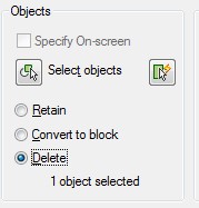
In the Objects area, enable the Delete button. (Figure Step 9)
Step 10
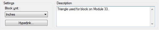
In the Settings area, set the Block unit to Inches and in the Description area, enter the description as shown in the figure. (Figure Step 10)
MUST KNOW: A block is a collection of drawing objects that acts as one object. Every drawing file has an invisible data area called the block definition table. The block definition table stores all the block definitions in that drawing. When a block is inserted into the drawing, it will reside on the current layer. A block can be exploded with theEXPLODE command. When a block is exploded, it loses all of its block properties and it is converted back to the original drawing objects and properties that it had when it was created.
Step 11
Except for the Base point, the Block Definition dialogue box should now match the figure. (Figure Step 11)
Step 12
Click OK and your drawing should now appear similar to the figure. (Figure Step 12)
Step 13
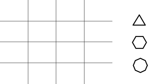
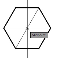
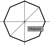
Using what you just learned, create a block from the hexagon and the octagon. For both, use the center of the object as the base point. To do that, you must first draw a construction line so that you can snap to its midpoint when specifying the base point. Ensure that you do not select the construction line as one of the block objects. Name the blocks: Module 33 Hexagon and Module 33 Octagon. (Figure Step 13A and 13B)
Step 14
Your drawing should now appear as shown in the figure. (Figure Step 14)
Step 15
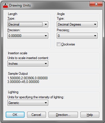
Enter the UNITS command. In the Drawing Units dialogue box, set the Insertion scale to Inches. (Figure Step 15)
Step 16
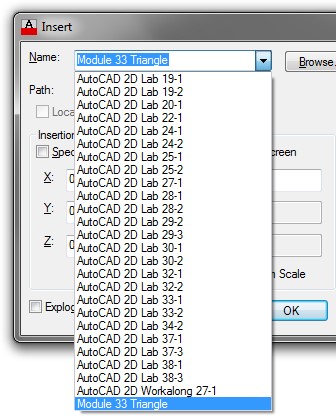
Set layer: 0 as the current layer. Enter the INSERT command to open the Insert dialogue box. In the Name: box, pull down the list and select the block: Module 33 Triangle. (Figure Step 16)
Step 17
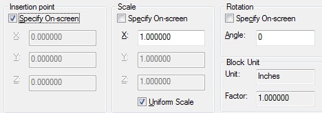
Set the Insert point, Scale and Rotation boxes as shown in the figure. (Figure Step 17)
Step 18
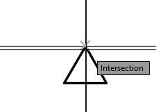
Click OK and when prompted for the insertion point, snap to the intersection of the upper left construction lines. (Figure Step 18)
Step 19
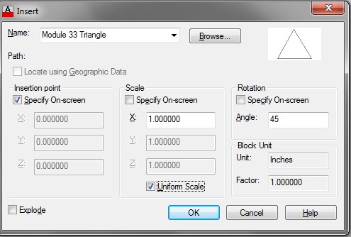
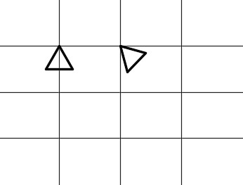
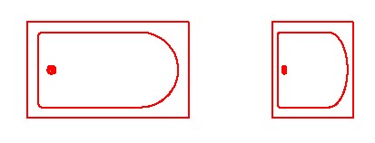
Enter the INSERT command and select the block: Module 33 Triangle. Set the Angle to 45. Insert the block locating the insertion point as shown in the figure. (Figure Step 19A and 19B)
Step 20
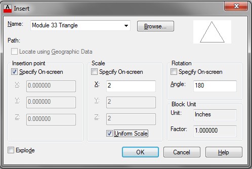
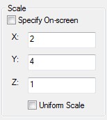
Enter the INSERT command and select the block: Module 33 Triangle. Set the Angle to 180, the X Scale to 2 and enable Uniform Scale. Insert the block as shown in the figure. (Figure Step 20A and 20B)
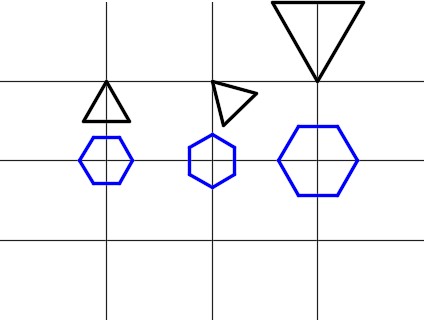
Step 21
Set layer: Blocks as the current layer. Using what you just learned, insert three: Module 33 Hexagon blocks locating the insert point at the intersections of the construction lines as shown in the figure. The left and center blocks are inserted at scale factor of 1 and the one on the right at a scale factor of 1.5. Set the appropriate angles to match the figure. (Figure Step 21)
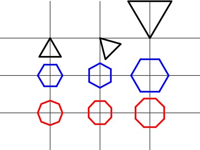
Step 22
Set layer: Object as the current layer. Using what you just learned, insert three: Module 33 Octagon blocks placing the insert point as shown in the figure. The left and center blocks are inserted at a scale factor of 1 and the one on the right at a scale factor of 1.25. Set the appropriate angle to match the figure. (Figure Step 22)
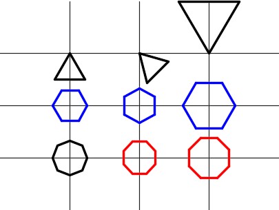
Step 23
Explode the left block: Module 33 Octagon as shown in the figure. (Figure Step 23)
Step 24
Turn layer: Construction off. (Figure Step 24)
Step 25
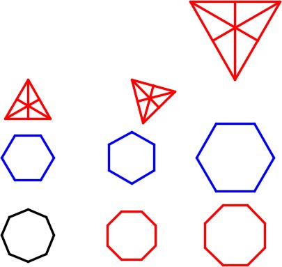
Insert a block: Module 33 Triangle anywhere in model space. Explode the block and change the objects to layer: Object. On layer: Object, draw lines from each corner to the midpoint of the opposite line. (Figure Step 25).

Step 26
Using the BLOCK command, create a block of the triangle that you created in Step 25. Assign it the name: Module 33 Triangle. Keep the same base point (top corner of triangle).
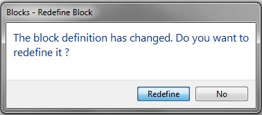
When you execute the command, the alert box will open warning you that a block with the same name is already defined in the drawing. Click Yes to accept. Take note how all of the blocks, named: Module 33 Triangle, will now display the new block definition. (Figure Step 26A and 26B)
Step 27
Save and close the drawing.
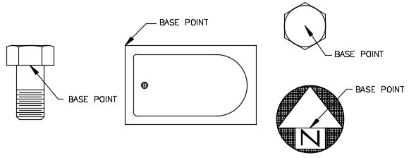
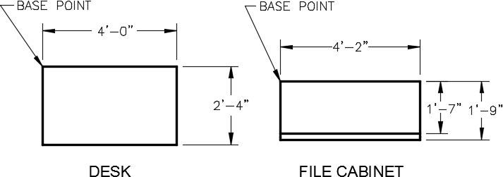
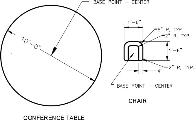
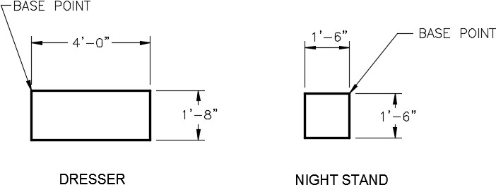
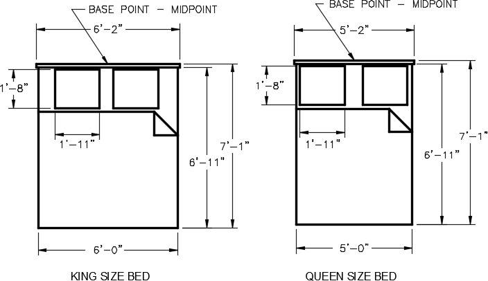
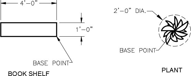
USER TIP:The location of the base point that is selected when creating a block is important. Each block is unique and has a best location for its base point. When selecting the location for a base point, imagine what location would be best when the block is inserted into a drawing. Study the blocks below and the base point locations that were selected for each of them.
Key Principles
Key Principles in Module 33
- A block is a collection of objects that acts as one object. Regardless of the number of times the block has been inserted into the drawing, it will not significantly change the size of the drawing’s database.
- The only way to remove a block from the block definition table is to purge it with the PURGE command.
- Layer 0 (zero), assigned the color black/white, is a special layer and color for blocks. A block that was created using objects drawn on layer 0 will reside on and take the properties of the layer it is inserted on.
Lab Exercise 33-1
Time allowed: 90 minutes.
| Drawing Name | Template | Units |
|---|---|---|
| AutoCAD 2D Lab 33-1 | N/A | Feet and /Inches |
Step 1
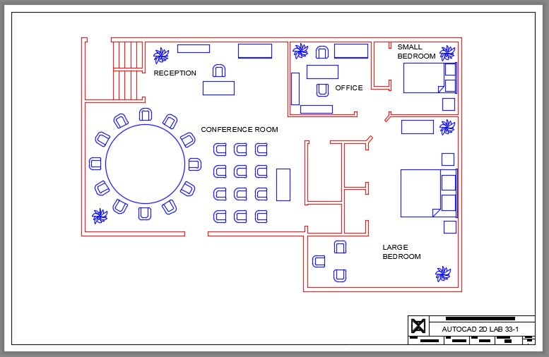
Open the drawing: AutoCAD 2D Lab 29-3. (Figure Step 1)
Step 2
Using the SAVEAS command, save and name the drawing: AutoCAD 2D Lab 33-1.
Step 3
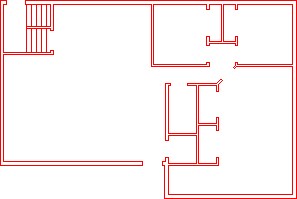
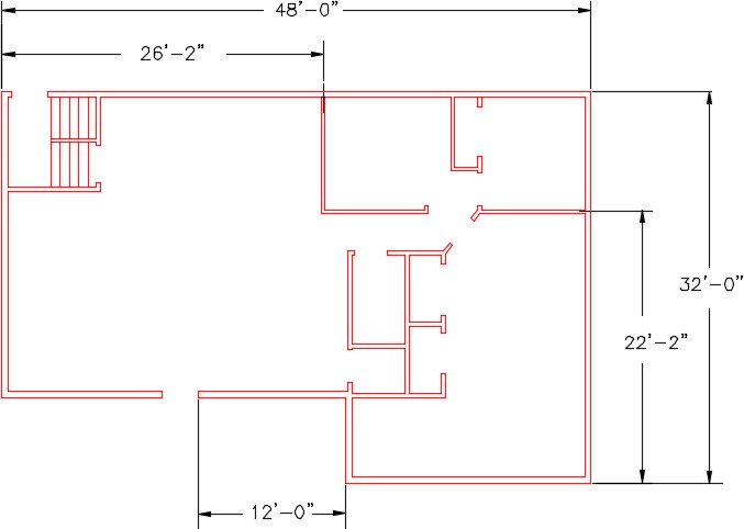
Make the changes to the floor plan as shown in the figure. Note the size changes and some walls were removed. Use the STRETCH command to make all of the size changes. (Figure Step 3)
Step 4
Draw the 10 objects shown in the figures anywhere in model space. Draw them on layer: 0. Ensure it is assigned the color Black/White. (Figure Step 4A and 4B)
Step 5
Create a block from each object. Use the following:
A Name the block as shown under the
B Set the BLOCK command to delete the blocks after
C Set the base point as shown on the
D Give the block a description and set the Block unit to
Step 6
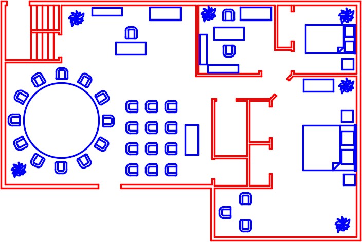
On layer: Furniture, insert the blocks as shown in the figure. Match the drawing the best that you can by eye. (Figure Step 6)
Step 7
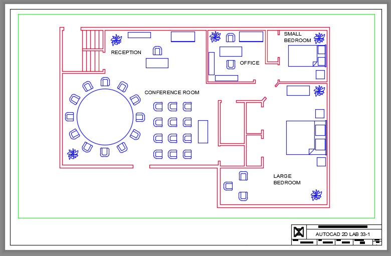
Enable layout: Module Layout D. On layer: Viewport, create a viewport setting its scale to 1/2″=1′-0″ and lock the display. In Paper space, on layer: Text, label the rooms as shown. Pick your own text size and font. Fill in the titleblock. (Figure Step 7)
Step 8
Turn layer: Viewport off to complete the drawing. (Figure Step 8)
Step 9
Save and close the drawing.
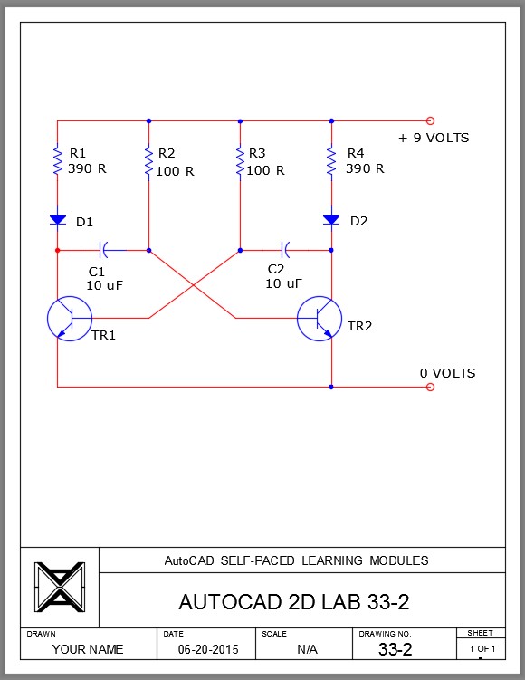
Lab Exercise 33-2
Time allowed: 30 minutes.
| Drawing Name | Template | Units |
|---|---|---|
| AutoCAD 2D Lab 33-2 | 2D Layout English | Inches |
Step 1
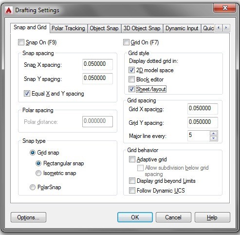
Open the Drafting Setting dialogue box. Set the grid and snap spacing to 0.05 units and any other settings to match the figure. Ensure that you disable the Adaptive grid and the Display grid beyond Limits box. (Figure step 1)
Step 2
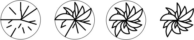
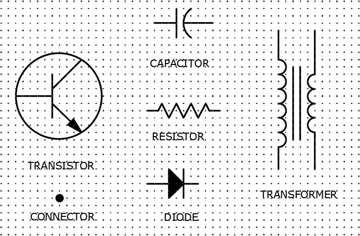
With the grid and snap enabled, draw the five symbols shown below anywhere in model pace. Draw them on layer 0. You will have zoom in close to draw the symbols. (Figure Step 2)
Step 3
Make a block of each symbol. Name them with the name shown below the drawing. Set the Block units to Inches. Delete the objects when you the block is created.
Step 4
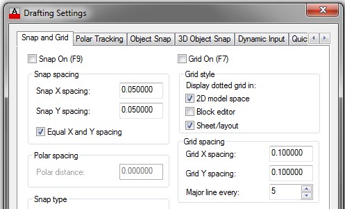
Set the grid to 0.1 and the snap to 0.05. (Figure Step 4)
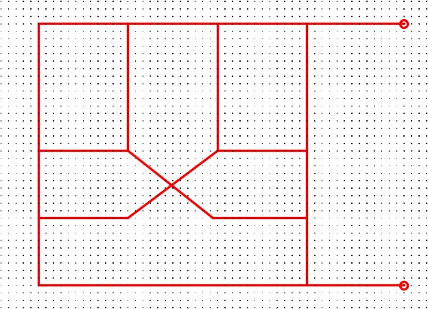
Step 5
On layer: Object, draw the lines and the terminating circles for the schematic diagram. Draw it by eye but do your best to match the figure. Ensure that you snap to grid point for the endpoints of all lines. (Figure Step 5)
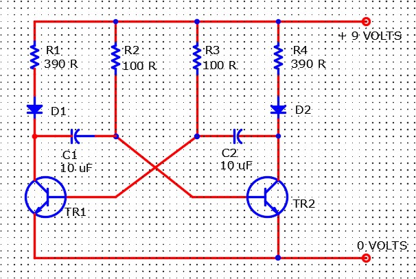
Step 6
On layer: Symbols, insert the blocks and trim the lines. (Figure Step 6)
Step 7
On layer: Viewport, create viewport setting the scale to 1.25:1 and lock the display. (Figure Step 7)
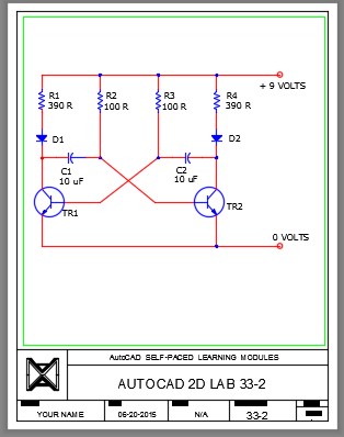
Step 8
In Paper space, on layer: Text, add the text as shown in the figure. Pick your own font and text height. Fill in the titleblock and turn layer: Viewport off to complete the drawing. (Figure step 8)