Module 7: Circles and Arcs
Learning Outcomes
When you have completed this module, you will be able to:
- Describe the geometry of circles and arcs.
- Apply the CIRCLE and ARC commands to draw circles and arcs.
- Describe how to undo a command or redo an undo.
Geometry Lesson: Circles
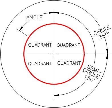
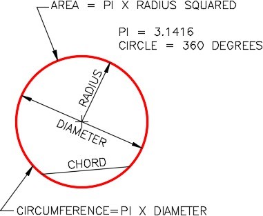
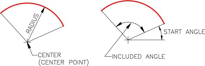
A circle is defined as a closed curve in which all points are the same distance from its center point. The center point is a single XY coordinate.
A circle is 360 degrees and can be divided into four quadrants. All points on a circle are at a given distance from is center point. The distance between any of the points and the center is called the radius.
Study the drawings in Figure 7-1, 7-2, 7-3, and 7-4 for a description of the geometry of a circle.
Geometry Lesson: Arcs
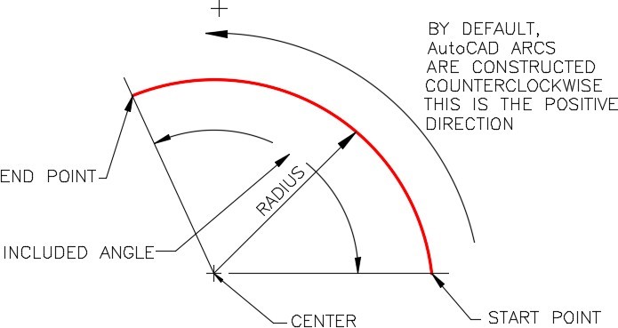
An arc is defined as an open curve in which all points are the same distance from its center point. Study the drawings in Figure 7-5 and 7-6.for a description of the geometry of an arc.
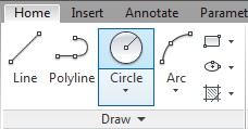
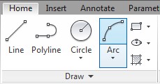
AutoCAD Command: CIRCLE
The CIRCLE command is used to draw circles.
Shortcut: C
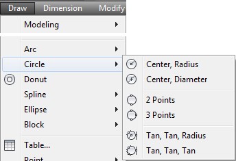
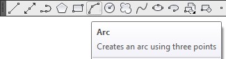
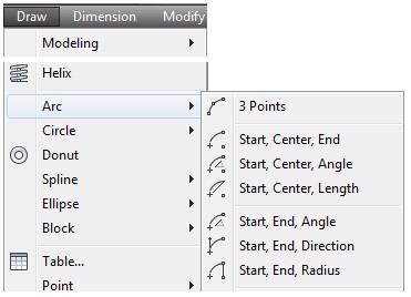
AutoCAD Command: ARC
The ARC command is used to draw arcs.
Shortcut: A
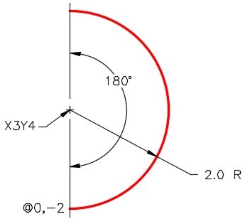
Command: ARC
Specify start point of arc or [Center]: C
Specify center point of arc: 3,4
Specify start point of arc: @0,-2
(Specifying the radius and the direction for the start point.)
Specify end point of arc or [Angle/chord Length]: A
Specify included angle: 180
Command:
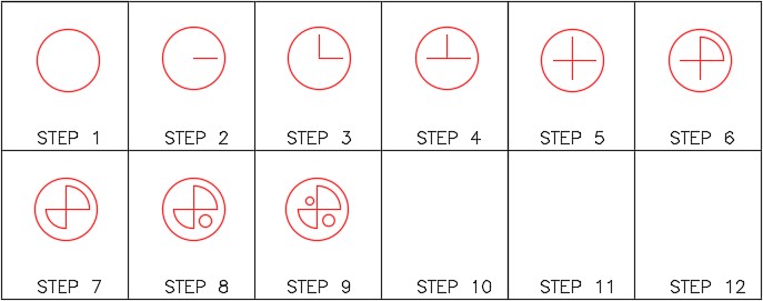
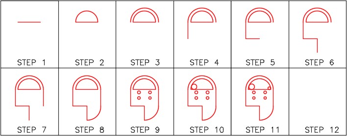
WORKALONG: Drawing Circles and Arcs
Step 1
Start a new drawing using the template: 2D English.
Step 2
Save and name the drawing: AutoCAD 2D Workalong 07-1.
Step 3
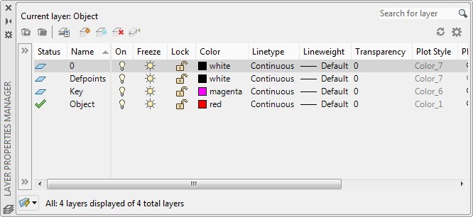
Create layer: Object, color red. Set it as the current layer. (Figure Step 3)
Step 4
Using the figures and what you already leaned, draw the two lines shown in Figure Step 4B. (Figure Step 4A and 4B)

Step 5
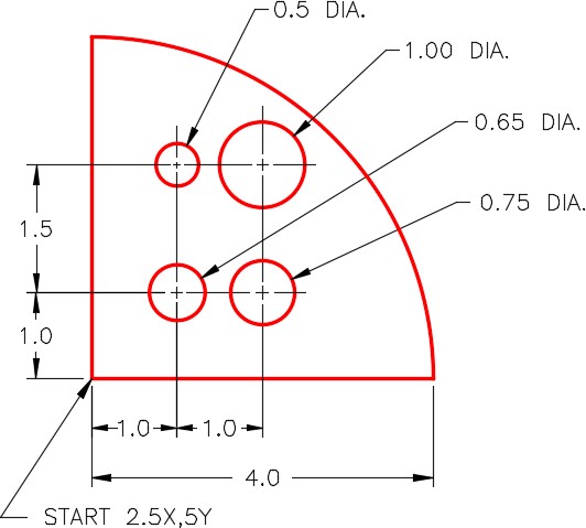
Enter the ARC command, as shown below, to draw the arc. (Figure Step 5)
Command: ARC
Specify start point of arc or [Center]: C
(If possible, always draw arcs starting with the center point first.)
Specify center point of arc: 2.5, 5
(Enter the center point.)
Specify start point of arc: @4,0
(Enter the start point. Here the trick is to give AutoCad the start point and the radius of the arc at the same time)
Specify end point of arc or [Angle/chord Length]: A
Specify included angle: 90
(Enter the angle of the arc. In this case, it is 90 degrees.)
Command:
Step 6
Enter the CIRCLE command, as shown below, to draw the four circles to complete the drawing. (Figure Step 6A and 6B)
Command: CIRCLE
Specify center point for circle or [3P/2P/Ttr (tan tan radius)]: 3.5,6
(Since this is the first circle, enter an absolute coordinate for the center point.)
Specify radius of circle or [Diameter]: D
(Circles are usually dimensioned with diameters rather then a radius, enter D)
Specify diameter of circle: 0.65
Command: CIRCLE
(Press Enter or Space bar as that will repeat the last command.)
Specify center point for circle or [3P/2P/Ttr (tan tan radius)]: @1,0
(Notice here, since AutoCAD always remembers the lastpoint, use an @. The lastpoint was the center of the first circle placed.)
Specify radius of circle or [Diameter] <0.3250>: D
Specify diameter of circle <0.6500>: 0.75
Command: CIRCLE (Press Enter or Space bar as that will repeat the last command.
Specify center point for circle or [3P/2P/Ttr (tan tan radius)]: @0,1.5
(Use an @ from the center of the last circle drawn.)
Specify radius of circle or [Diameter] <0.3750>: D
Specify diameter of circle <0.7500>: 1
Command: CIRCLE
(Press Enter or Space bar. That will repeat the last command and save you entering it again.)
Specify center point for circle or [3P/2P/Ttr (tan tan radius)]: @-1,0
Specify radius of circle or [Diameter] <0.5000>: D
Specify diameter of circle <1.0000>: 0.5
Command:
Step 7
Save and close the drawing.
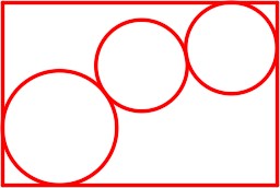
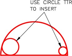
WORKALONG: Drawing Circles Using the TTR Option
Step 1
Start a new drawing using the template: 2D English.
Step 2
Save and name the drawing: AutoCAD 2D Workalong 07-2.
Step 3
Create layer: Object, color red. Set it as the current layer. (Figure Step 3)

Step 4
Using the dimensioned drawing as a guide and what you already learned, use the LINE command to draw the four outside lines. (Figure Step 4A and 4B)

Step 5
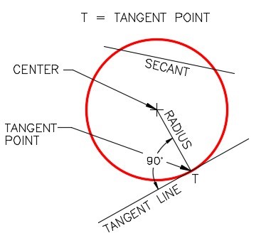
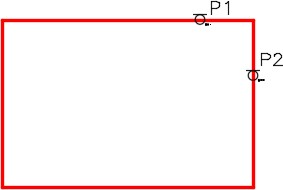
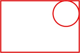
Enter the CIRCLE command and the TTR option, as shown below, to insert the 2 inch diameter circle. (Figure Step 5A and 5B)
Command: CIRCLE
Specify center point for circle or [3P/2P/Ttr (tan tan radius)]: TTR
Specify point on object for first tangent of circle: P1
(Using the graphic cursor, move it on the top horizontal line. When the tangent snap icon appears, press the left mouse button.)
Specify point on object for second tangent of circle: P2
(Move the cursor on the vertical line. When the tangent icon appears, pick it.)
Specify radius of circle <0.7000>: 1
(Enter the radius of the circle. Be careful, since circles are usually dimensioned in diameters you will have to divide it in half.)
Command:
Step 6
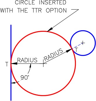
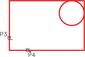
Enter the CIRCLE command and the TTR option, as shown below, to insert the 2.5 inch diameter circle. (Figure Step 6A and 6B)
Command: CIRCLE
Specify center point for circle or [3P/2P/Ttr (tan tan radius)]: TTR
Specify point on object for first tangent of circle: P3 Specify point on object for second tangent of circle: P4 Specify radius of circle <1.0000>: 1.25
Command:
Step 7
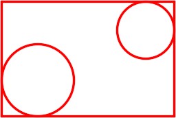
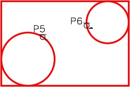
Enter the CIRCLE command and the TTR option, as shown below, to insert the middle 2 diameter circle. (Figure Step 7A and 7B)
Command: CIRCLE
Specify center point for circle or [3P/2P/Ttr (tan tan radius)]: TTR
Specify point on object for first tangent of circle: P5
Specify point on object for second tangent of circle: P6
Specify radius of circle <1.2500>: 1
Command:
Step 8
Save and close the drawing.
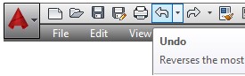
MUST KNOW: A very useful feature in AutoCAD is being able to undo a command or redo an undo. All of the commands in the current drawing session can be undone, one at a time. The last undo only can be reversed with a redo.To undo the last command, enter the U command, press CTRL+Z, or click the icon as shown in the figure on the right.
Command: U
If more then one U is entered, it will step back one command at time. This is useful if you made an error several commands earlier.
Command: U
Command: U
Command: U
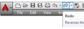
Enter the REDO command, press CTRL+Y, or click the icon as shown in the figure on the right to redo the undo. The redo will undo the last undo only.
Command: REDO
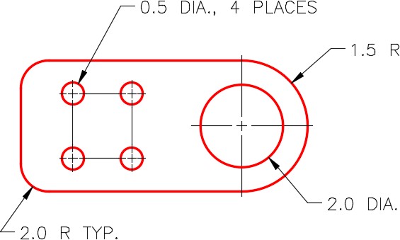
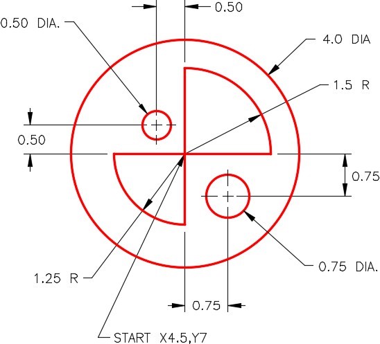
Drafting Lesson: Reading Dimensions for Circles and Arcs
Circles and arcs are dimensioned as follows:
Circles are dimensioned with their diameter. For example: 2.0 DIA.
Arcs are dimensioned with their radius.
For example: 1.5 R
When there is more than one circle of the same diameter, it is only dimensioned once. For example: 0.5 DIA., 4 PLACES
Sometimes multiple arcs are dimensioned as typical (TYP.). For example: 2.0 R TYP. Typical simply means that there is at least one more arc of the same size. See Figure 7-8
Key Principles
Key Principles in Module 7
- A circle is 360 degrees and can be divided into four quadrants.
- All points on a circle are at a given distance from is center point.
- An arc is defined as an open curve in which all points are the same distance from its center point.
- By default, AutoCAD draws arcs counterclockwise.
- When drawing arcs it is best to specify the center point first, the start point that sets the radius second, and an angle to locate the endpoint third.
- A very useful feature in AutoCAD is being able to undo a command or redo an undo.
Lab Exercise 7-1
Time allowed: 40 minutes.
| Drawing Name | Template | Units |
|---|---|---|
| AutoCAD 2D Lab 07-1 | 2D English | Inches |
| Layer Name | Objects on Layer | Color |
|---|---|---|
| Object | All lines, circles and arcs | Red |
Step 1
Start a new drawing using the template shown above.
Step 2
Save and name the drawing with the name shown above.
Step 3
Setup the layers using the Layering Scheme shown above.
Step 4
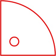
Draw the object shown in the figure. In this drawing, all objects should be on layer: Object and display red. (Figure Step 4A and 4B)

Completed Drawing
Step 5
Enter the UNITS command. In the Units dialogue box, set the Insertion Units to Inches.
Step 6
Check the drawing’s accuracy with the key.
Step 7
If there are any errors, turn layer: Key off and correct the drawing. If necessary, start a new drawing and draw it again.
Step 8
Turn layer Key on. If the drawing still inaccurate, go back to Step 7.
Step 9
Turn layer Key off.
Step 10
Save and close the drawing.
Hint 1
(Figure Hint 1)
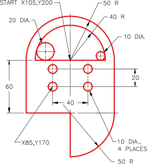
Lab Exercise 7-2
Time allowed: 40 minutes.
| Drawing Name | Template | Units |
|---|---|---|
| AutoCAD 2D Lab 07-2 | 2D Metric | Millimeters |
| Layer Name | Objects on Layer | Color |
|---|---|---|
| Object | All lines, circles and arcs | Red |
Step 1
Start a new drawing using the template shown above.
Step 2
Save and name the drawing with the name shown above.
Step 3
Setup the layers using the Layering Scheme shown above.
Step 4
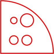
Draw the object shown in the figure. In this drawing, all objects should be on layer: Object and display red. (Figure Step 4A and 4B)
Completed Drawing
Step 5
Enter the UNITS command. In the Units dialogue box, set the Insertion Units to Millimeters.
Step 6
Check the drawing’s accuracy with the key.
Step 7
If there are any errors, turn layer Key off and correct the drawing. If necessary, start a new drawing and draw it again.
Step 8
Turn layer: Key on. If the drawing still inaccurate, go back to Step 7.
Step 9
Turn layer: Key off.
Step 10
Save and close the drawing.
Hint 1
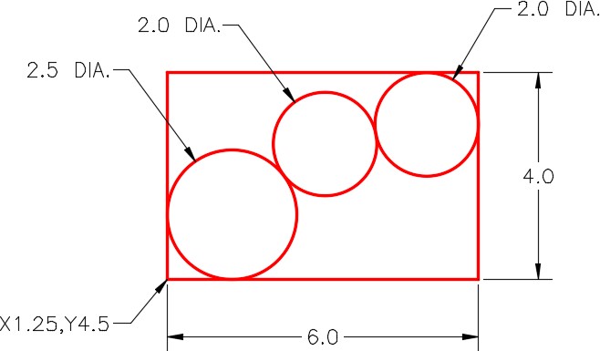
Draw the two circles using the TTR option. (Figure Hint 1)
Hint 2
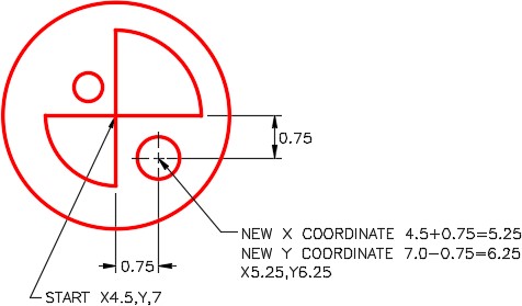
Draw the four smaller circles using the @ as shown below. (Figure Hint 2)
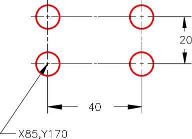
Command: C
CIRCLE Specify center point for circle or [3P/2P/Ttr (tan tan radius)]: 85,170
Specify radius of circle or [Diameter]: D
Specify diameter of circle: 10
Command: C
CIRCLE Specify center point for circle or [3P/2P/Ttr (tan tan radius)]: @40,0
Specify radius of circle or [Diameter] <5.0000>:
Command: C
CIRCLE Specify center point for circle or [3P/2P/Ttr (tan tan radius)]: @0,20
Specify radius of circle or [Diameter] <5.0000>:
Command: C
CIRCLE Specify center point for circle or [3P/2P/Ttr (tan tan radius)]: @-40,0
Specify radius of circle or [Diameter] <5.0000>:
Command:
