Module 31: Competency Test 6 Open Book
Learning Outcomes
When you have completed this module, you will be able to:
- Within a two hour time limit, complete a written exam and a lab exercise without the aid of a key.
The AutoCAD 2D book was written with competency based modules. What that means is that you have not completed each module until you have mastered it. The Competency Test module contains multiple choice questions and a comprehensive lab exercise to test your mastery of the set of modules that you completed. There are no answers or keys supplied in a Competency Test module since it is meant to be checked by your instructor. If there are any parts of this module that you have trouble completing, you should go back and reread the module or modules containing the information that you are having trouble with. If necessary, redo as many lab exercises required until you fully understand the material.
If you are Completing this book:
- Without the Aid of an Instructor, complete the written test and the lab exercise.
- In a Classroom with an Instructor, the instructor will give instructions on what to do after this module has been completed.
Multiple Choice Questions
Select the BEST answer.
- Which one of the following commands can be used to find the perimeter of a closed polyline?
- PERIMETER
- AREA
- DIST
- INQUIRY
- LENGTH
- Which one of the following commands can be used to control the size the grid displays on a drawing? Select the best answer.
- POINT
- SNAP
- UNITS
- LIMITS
- PEDIT
- Which one of the following commands can be used to convert a polyline back to its original objects?
- ERASE
- EXPLODE
- PEDIT
- BOUNDARY
- POLYGON
- Which two of the following commands can be used to toggle a pline’s width off and on?
- FILL and EXPLODE
- PEDIT and FILL
- REGEN and PEDIT
- EXPLODE and FILL
- FILL and REGEN
- What are the minimum and maximum number of sides that a polygon can be drawn using the POLYGON command?
- 3 and 512
- 3 and 1024
- 3 and 256
- 4 and 2048
- 4 and 1024
- Which one of the following function keys toggles snap mode?
- F5
- F6
- F7
- F8
- F9
- Which one of the following commands can be used to draw a square as a closed polygon?
- INSERT
- SQUARE
- RECTANGLE
- BLOCK
- FILL
- Which two commands can be used to toggle the display of a donut’s solid fill off and on?
- FILL and EXPLODE
- PEDIT and FILL
- FILL and REGEN
- EXPLODE and FILL
- REGEN and PEDIT
- Which one of the following function keys toggles the grid display?
- F5
- F6
- F7
- F8
- F9
- When the PEDIT command is used to create a pline, what are the only two types of drawing objects that can be selected by the user?
- ellipses and arcs
- arcs and circles
- lines and arcs
- lines and circles
- lines and ellipses
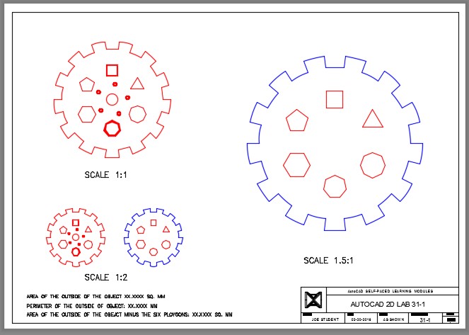
Lab Exercise 31-1 Open Book
| Drawing Name | Template | Units |
|---|---|---|
| AutoCAD 2D Lab 31-1 | 2D Layout Metric | Millimeters |
Step 1
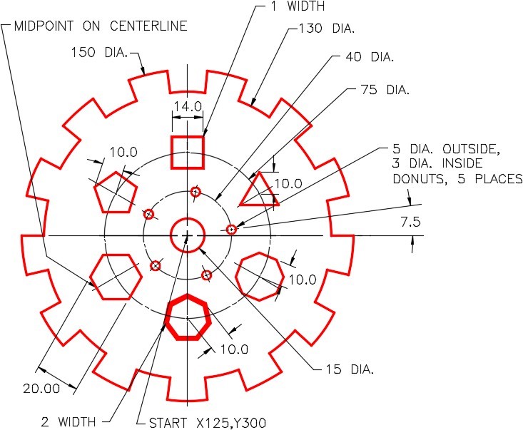
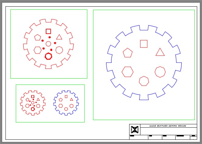
On layer: Object, draw the object shown in the figures. (Figure Step 1A and 1B)
Step 2
Change the width of the two regular polygons to a width of 1 and 2 as shown in Figure Step 1B)

Completed Drawing
Step 3
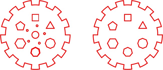
Copy all objects, except the circles, 200 mm to the right. (Figure Step 3)

Step 4
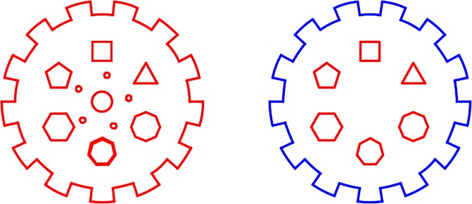
Using the PEDIT command, change the widths of all plines, in the copied figure, to the width of 0. (Figure Step 4)
Step 5
On layer: Boundary, create a closed polyline of the outside perimeter of the copied object. (Figure Step 5)
Step 6
Enable layout: Module Layout A2. On layer: Viewport, create three viewports. Set the scale of the viewports as shown in the figure and lock their display. (Figure Step 6)
Step 7
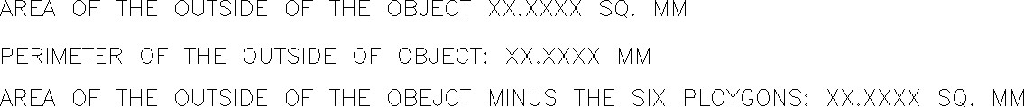
Find the areas and perimeter shown in the figure. Set the current text style to: 2D Modules. In Paper space, on layer: Text, insert the text in the bottom left corner of the layout and include your answers. Set a text height that appears best on the drawing. (Figure Step 7)
Step 8
In Paper space, on layer: Text, insert the scales of each viewport as shown in the figure. Set a text height that appears best on the drawing.
Step 9
On layer: Titleblock Text, fill in the titleblock using the standard shown in Module 20.
Step 10
Turn layer: Viewport off. (Figure Step 10)