Module 13: Object Properties
Learning Outcomes
When you have completed this module, you will be able to:
- Describe object properties, linetype, and linetype scale.
- Describe how to assign and edit linetypes ByLayer and set their linetype scale.
- Apply the PROPERTIES and LTSCALE commands to display and edit properties of drawing objects and set the linetype scale of objects.
- Describe how to select objects using a pick, a window, and a crossing window.
Object Properties

Properties of a Line
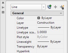
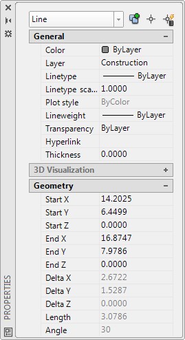
AutoCAD stores all existing objects and their properties in a database file called the drawing file. The name of the file is the drawing name that you assigned to the drawing and AutoCAD automatically assigns the extension .dwg. The drawing file stores all existing drawing objects along with the properties of each object in a database. The drawing objects that have been taught up to now are lines, circles, and arcs. Figure 13-1 displays the properties of a line.
When an existing drawing is opened, AutoCAD reads the drawing file and uses it to construct the objects from the database and displays the objects in the Graphic window. The REGEN command does the same thing for the current drawing.
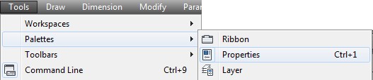
The PROPERTIES command opens the Properties window. Properties of existing drawing objects can be modified using commands or they can be edited in the Properties window. It is faster and easier to edit the properties in the Properties window but not all of the properties can be edited using it. AutoCAD grays the boxes of the properties that cannot be changed in the window. See Figure 13-1.
Without entering a command, one or more objects in the current drawing can be selected using the pick box. The selected object(s) will highlight and the data will appear in the Properties window. If more then one object is selected, only the properties which are common to all of the selected objects will display. To unselect objects, press the Esc key.
Figure 13-2 shows the Properties window where only one line was selected by the user. This can be seen in the box located in the top left corner of the window. This box will display what object(s) is currently selected and its properties are displayed below in the window.
The Properties Dialogue Box
Linetypes
A linetype is a repeating pattern of dots, dashes, text, objects, or blank spaces displayed on a drawing object. Up to this point in the book, the default linetype Continuous has been assigned to all objects. See Figure 13-3. A continuous linetype displays solid. In this module, linetypes will be assigned ByLayer. The template files that you are using are only loaded with the Continuous linetype. Before a linetype can be assigned to a layer, it must be loaded into the current drawing’s database. All loaded linetypes will remain in the drawing file for future use. If required, they can be purged out of the drawing file. Purging is taught in Module 34.
Continuous Linetype
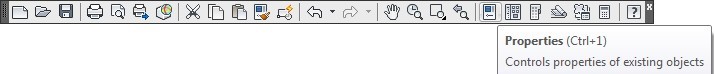
AutoCAD Command: PROPERTIES
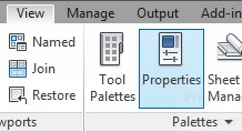
The PROPERTIES command opens the Properties window.
Shortcut: CTRL+1
AutoCAD Command: LTSCALE
The LTSCALE system variable is used to set the global linetype scale for the drawing.
Shortcut: LTS
MUST KNOW: Before AutoCAD displays the linetype on a drawing object, it multiplies the scale factor set in LTSCALE times the linetype scale property that is assigned to the drawing object.
For example, if the LTSCALE is set to 5 and the drawing object’s linetype scale property is set to 2, AutoCAD will display the object with the linetype scale of 10. In other words, it will display the linetype 10 times larger then its normal display.
It is best to set the LTSCALE to 1 and set the drawing object’s linetype scale property to the setting to display the desired linetype and that makes it easier for you to set the linetype scale.
For example, if the LTSCALE is set to 1 and the objects linetype scale property is set to 10, AutoCAD will display the drawing object with the linetype scale of 10 or 10 times its normal display.
WORKALONG: Working with Linetypes and Linetype Scales
Step 1
Start a new drawing using template: 2D English.
Step 2
Save and name the drawing: AutoCAD 2D Workalong 13-1.
Step 3
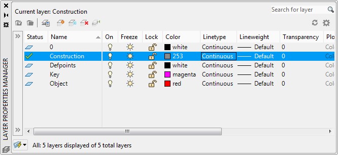
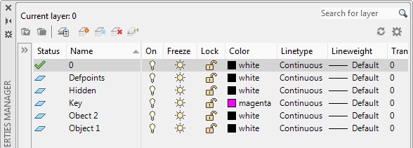
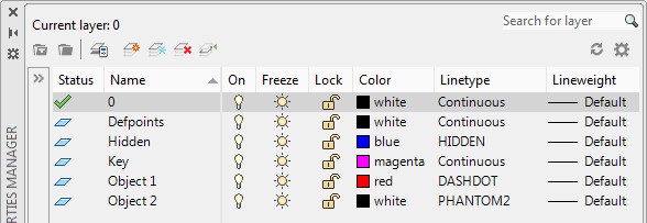
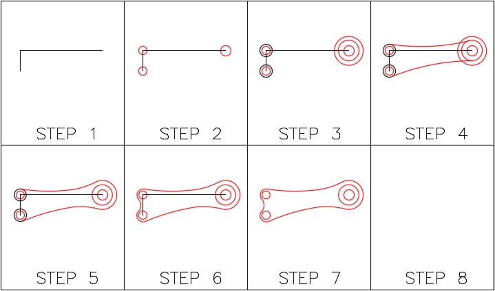
Open the Layer Properties Manager window and create the layers: Hidden, Object 1, and Object 2. (Figure Step 3)
Step 4
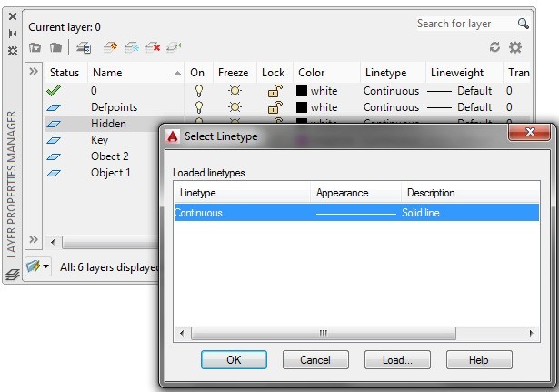
Click layer: Hidden to select it. Select Continuous. This will open the Select Linetype dialogue box. (Figure Step 4)
Step 5
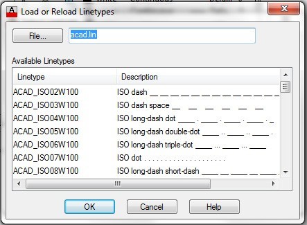
Click the Load button to open the Load or Reload Linetypes dialogue box. The name in the File box will be one of the following: (Figure Step 5).
ACAD.LIN – English
ACADISO.LIN – Metric
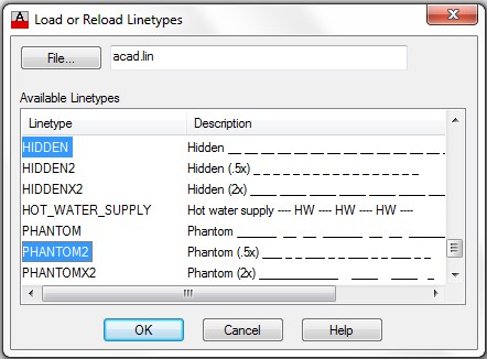
Step 6
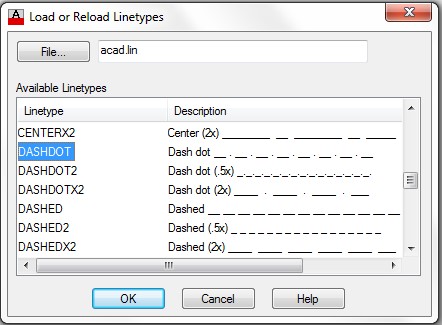
Scroll down until you find the linetype: DASHDOT. Select it as shown in the figure. (Figure Step 6)
Step 7
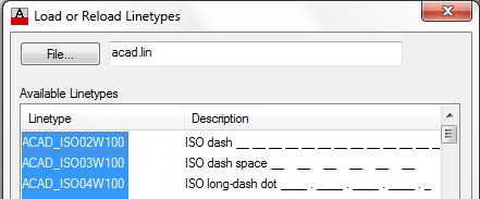
While holding down the Ctrl key, scroll down until you find the linetypes: HIDDEN and PHANTOM2. Select them. They will highlight as shown in the figure. Click OK to close the dialogue box. (Figure Step 7).
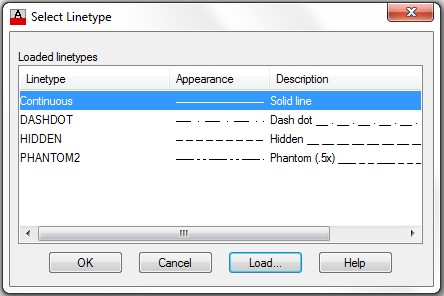
Step 8
The linetypes you selected in Step 7 will display in the Select Linetype dialogue box. Click OK to close the dialogue box. (Figure Step 8)
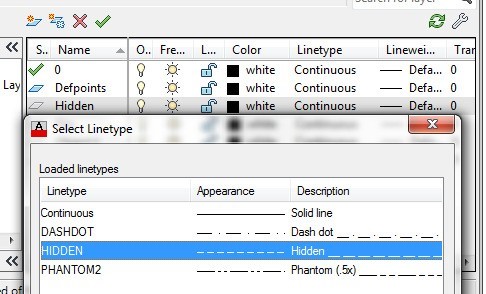
Step 9
In the Layer Properties Manager window, click layer: Hidden and click the linetype: Continuous. In the Select Linetype dialogue box, select the linetype: HIDDEN and then click OK. (Figure Step 9)
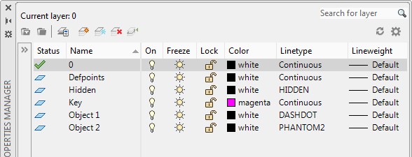
Step 10
Using what you just learned, change the linetype for layer: Object 1 to linetype: DASHDOT and layer: Object 2 to the linetype: PHANTOM2. (Figure Step 10)
Step 11
Change the colors of the layer: Hidden to blue and layer: Object 1 to red to match the figure. (Figure Step 11)
Step 12
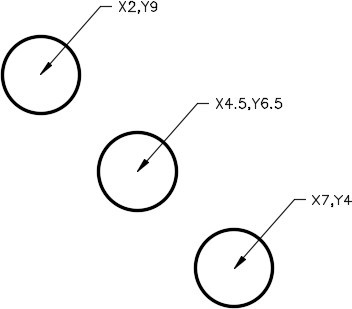
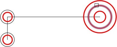
Draw three 2-inch diameter circles on layer 0 locating their centers at the coordinates shown in the figure. (Figure Step 12)
Step 13
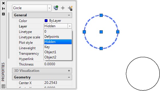
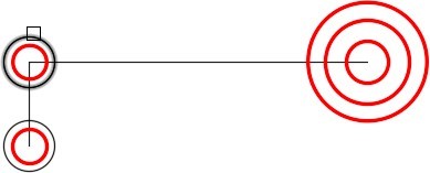
Open the Properties window and select the top left circle. While it is selected, change it to layer: Hidden as shown in the figure. (Figure Step 13)
Step 14
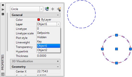
Select the center circle. In the Properties window, change it to layer Object 1. (Figure Step 14)
Step 15
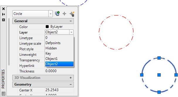
Select the bottom right circle. In the Properties window, change it to layer: Object 2. Your drawing should now appear as shown in figure. (Figure Step 15A and 15B)
Step 16
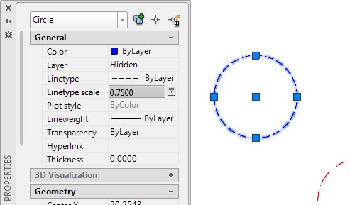
Select the top left circle. In the Properties window, change the Linetype scale property to 0.750. (Figure Step 16)
Step 17
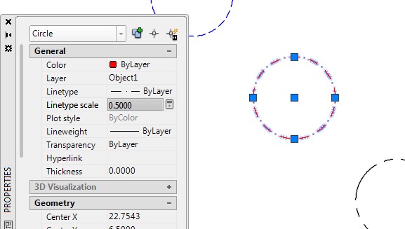
Select the middle circle. In the Properties window, change the Linetype scale property to 0.500. (Figure Step 17)
Step 18
Select the bottom circle. In the Properties window, change the Linetype scale property to 1.500. (Figure Step 18)
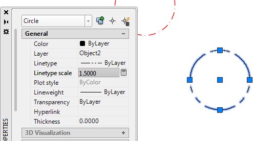
Step 19
Enter the LTSCALE system variable as shown below and ensure that it is set to 1.
Command: LTSCALE
Enter new linetype scale factor <1.0000>:
Command:
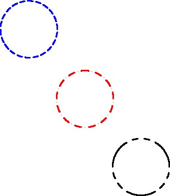
Step 20
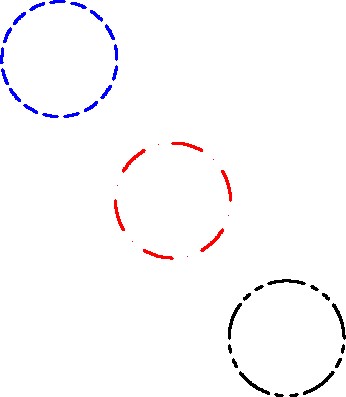
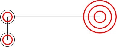
Your completed drawing should appear as shown in the figure. (Figure Step 20)
Step 21
Save and close the drawing.
Selecting Objects
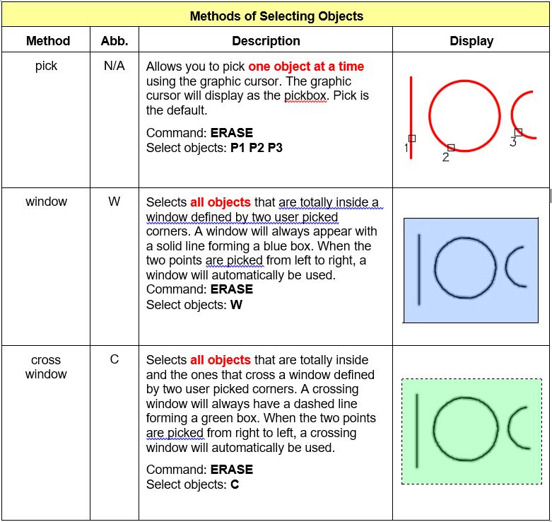
After entering a command that requires you to select one or more objects, AutoCAD will display the Select object: prompt. To draw faster, it is important for you to be able to select objects in the most time efficient method since many commands require object selection. There are many methods of selecting objects and they will be taught in future module. In this module, the pick, window, and crossing window methods are taught. See Figure 13-4.
WORKALONG: Selecting Objects
Step 1
Open the drawing: AutoCAD 2D Lab 12-2. (Figure Step 1)
Step 2
Using the SAVEAS command, save and name the drawing:
AutoCAD 2D Workalong 13-2.
Step 3
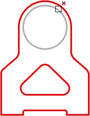
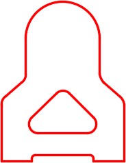
Enter the ERASE command as shown below. When you are prompted to Select objects, select the circle with the pickbox and press the Enter key. (Figure Step 3A and 3B)
Command: ERASE
Select objects:
Command:
Step 4
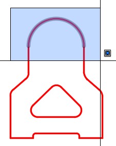
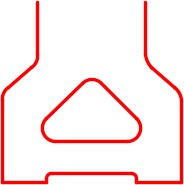
Enter the ERASE command. When prompted to Select objects, select two locations to form a window. You must select the locations on opposite corners from left to right. A window is colored blue and has a solid line around it. Press Enter to execute the command. (Figure Step 4A and 4B)
Step 5
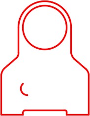
Enter the U command to undo that last command. The arc you just erased will redisplay on the drawing. (Figure Step 5)
Step 6
Enter the ERASE command. When you are prompted with the Select objects prompt, select two locations moving from right to left. The two locations must be the opposite corners of the crossing window. Press Enter to execute the command. (Figure Step 6A and 6B)
Step 7
Enter the U command as many times as required to display the drawing as shown in the figure. (Figure Step 7)

Step 8
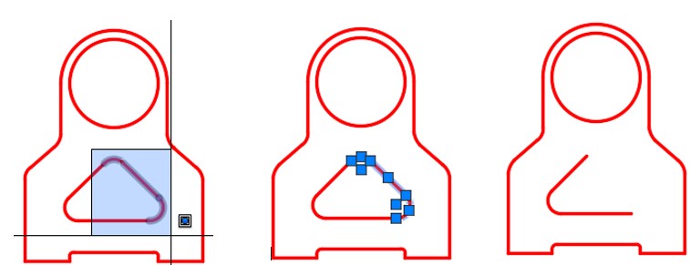
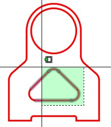
Without entering a command and using what you learned earlier, place a window as shown in the figure. All of the objects that are totally inside the window will highlight and display grips. Press the Delete key to delete the objects. (Figure Step 8A, 8B, and 8C)
Step 9
Enter the U command to undo that last command. The arcs and line you just erased will redisplay on the drawing.
Step 10
Without entering a command and using what you learned earlier, place a crossing window as shown in the figure. All of the objects that cross the window and all of the objects that are totally inside the window will be selected and display grips. Press the Delete key to delete the objects. (Figure Step 10A, 10B, and 10C)
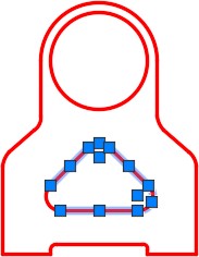
Step 11
Enter the U command to undo that last command.
Step 12
Save and close the drawing.
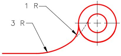
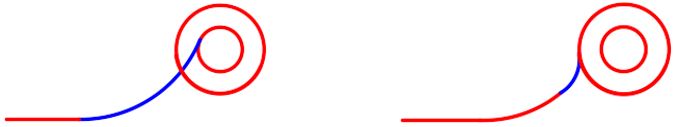
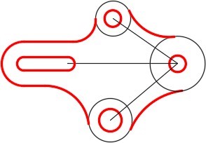
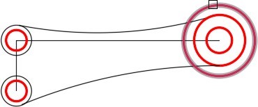
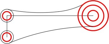
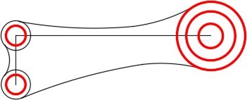
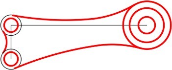
Geometry Lesson: A Compound Fillet
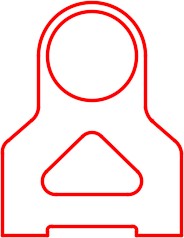
A compound fillet is two or more tangent arcs used to create a continuous curve. Study Figure 13-5. Note the small dashed line. It is a drafting standard to indicate that the 3 R (Radius) arc is tangent to the line and small circle as shown in Step 1. The 1 R tangent arc is then inserted tangent to 3 R arc and the large circle as shown in Step 2. Since they are tangent arcs, you would use the FILLET command, two times, to draw them.
A Compound Fillet
Key Principles
Key Principles in Module 13
- AutoCAD stores all existing drawing objects and their properties in a database file called the drawing file. The name of the file is the drawing name with the extension .dwg.
- A linetype is a repeating pattern of dots, dashes, text, objects, or blank spaces displayed on the object. It is an appearance only and does not change the object in any way.
- The individual linetype scale property multiplies the scale factor it is set to times the existing scale factor of the global linetype scale (LTSCALE). It is best to set LTSCALE to 1 at all times.
- If you use the pick method to select the objects, AutoCAD will select only one object, even though two objects are exactly located at the same location. If the same objects are selected using either the window or cross window method, AutoCAD will select all objects even if they are at the exact same location.
Lab Exercise 13-1
Time allowed: 30 minutes.
| Drawing Name | Template | Units |
|---|---|---|
| AutoCAD 2D Lab 13-1 | 2D English | Inches |
| Layer Name | Objects on Layer | Color |
|---|---|---|
| Construction | Construction objects | 253 |
| Object | All objects | Red |
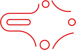
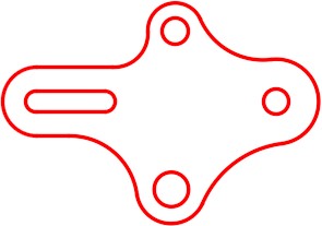
Step 1
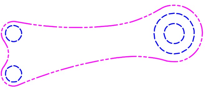
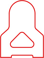
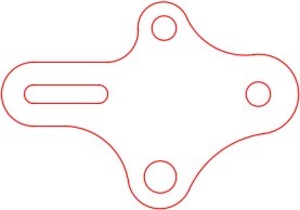
Draw the object shown in the figure using the layering scheme. (Figure Step 1A and 1B)

Completed Drawing
Step 2
Set the insertion units and check your drawing with the key.
Step 3
Turn layer: Key off and freeze layer: Construction.
Step 4
Save and close the drawing.
Hint 1
See the following step:
Step 1
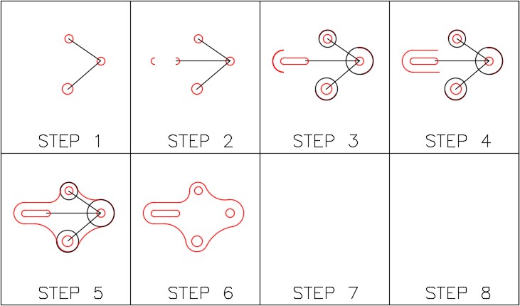
Draw the lines, circles and arcs as shown in the figure. (Figure Hint Step 1)
Step 2
Draw two horizontal lines, of any length, starting at the ends of the arc on the left. (Figure Hint Step 2)
Step 3
Insert a 1 radius fillet between the horizontal line and the circle. (Figure Hint Step 3)
Step 4
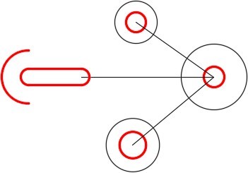
Insert a 2 radius fillet between the two circles on the top right and another one between the horizontal line and circle on the bottom left. (Figure Hint Step 4)
Step 5
Insert a 3 radius fillet between the two circles on the bottom right. (Figure Hint Step 5)
Step 6
Using the Properties window, change the layer of the arcs to layer: Object. (Figure Hint Step 6)
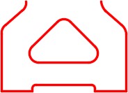
Step 7
Freeze layer: Construction. (Figure Hint Step 7)
Step 8
Using the FILLET command, insert three fillets, using the applicable radius, between the arcs. (Figure Hint Step 8)
Lab Exercise 13-2
Time allowed: 20 minutes.
| Drawing Name | Template | Units |
|---|---|---|
| AutoCAD 2D Lab 13-2 | N/A | N/A |
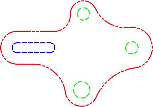
| Layer Name | Objects on Layer | Color | Line Type |
|---|---|---|---|
| Outline | Outline of object | Red | Phantom 2 |
| Circle | Full circles | Green | Border 2 |
| Slot | The slot | Blue | Dashed 2 |
Step 1
Open the drawing: AutoCAD 2D Lab 13-1.
Step 2
Using the SAVEAS command, save the drawing with the name: AutoCAD 2D Lab 13-2.
Step 3
Open the Layer Property Manager window and change the linetypes of the layers to match the layering scheme shown above.
Step 4
Using the Properties window, change the layers of the objects to match the layering scheme shown above.
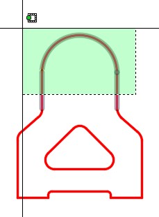
Step 5
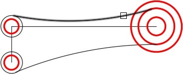
Change the linetype scale of each object to match the figure. (Figure Step 5)
Lab Exercise 13-3
Time allowed: 30 minutes.
| Drawing Name | Template | Units |
|---|---|---|
| AutoCAD 2D Lab 13-3 | 2D Metric | Millimeters |
| Layer Name | Objects on Layer | Color |
|---|---|---|
| Construction | Construction objects | 253 |
| Object | All objects | Red |
Step 1
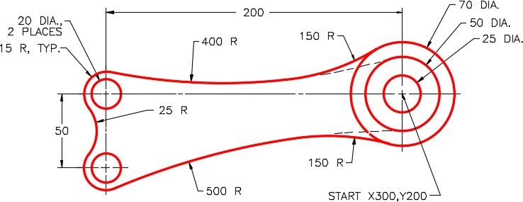
Draw the object shown in the figure using the layering scheme. (Figure Step 1A and 1B)
Step 2
Set the insertion units and check your drawing with the key.
Step 3
Turn layer: Key off and freeze layer: Construction.
Step 4
Save and close the drawing.

Completed Drawing
Hint 1
See the following steps:
Step 1
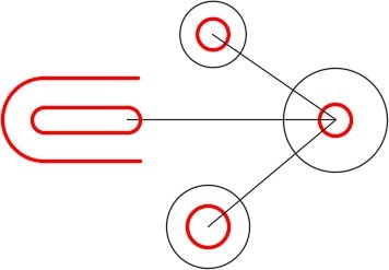
Draw the lines and circles as shown in the figure. (Figure Hint Step 1)
Step 2
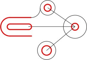
Enter the FILLET command and set the radius to 400. For the first object, select the large circle on the left. For the second object, select the middle circle on the right. (Figure Hint Step 2A, 2B, and 2C)
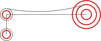
Step 3
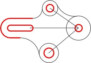
Using what you learned in Step 2, insert the compound bottom fillet. You will have to change the radius to 500. (Figure Hint Step 3)
Step 4
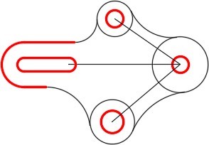
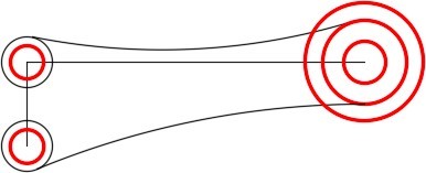
Enter the FILLET command and set the radius to 150. For the first object, select the fillet inserted in Step 2. For the second object, select the large circle on the right. Figure Hint Step 4A, 4B, and 4C)
Step 5
Using what you learned in Step 4, insert the fillet on the bottom. (Figure Hint Step 5)

Step 6
Insert a 25 radius fillet between the circles on the left. (Figure Hint Step 6)
Step 7
Change the layer of the fillets to layer: Object. (Figure Hint Step 7)
Step 8
Freeze layer: Construction. (Figure Hint Step 8)
Step 9
Insert two 15 radius fillets between the arcs on the left. (Figure Hint Step 9)

Lab Exercise 13-4
Time allowed: 20 minutes.
| Drawing Name | Template | Units |
|---|---|---|
| AutoCAD 2D Lab 13-4 | N/A | N/A |
| Layer Name | Objects on Layer | Color | Line Type |
|---|---|---|---|
| Circles | All circles | Blue | Dashed |
| Arcs | All arcs | Magenta | Phantom |
Step 1
Open the drawing: AutoCAD 2D Lab 13-3.
Step 2
Using the SAVEAS command, save the drawing with the name: AutoCAD 2D Lab 13-4.
Step 3
Open the Layer Property Manager window and change the linetypes of the layers to match the layering scheme shown above.
Step 4
Using the Properties window, change the layers of the objects to match the layering scheme shown above.
Step 5
Change the linetype scale of each object to match the figure. (Figure Step 5)